Potentiometers and Encoders For Electronics Projects
In this post, we'll dive deep into the mechanics of rotary encoders and potentiometers and provide some simple code.
While both devices are essential for measuring rotational movement, they have distinct ways of operating. Rotary encoders generate digital signals, capturing both the degree of rotation and its direction – perfect for projects where precision is key. Potentiometers act as variable resistors, offering an analog output that's invaluable for its simplicity.
Potentiometers
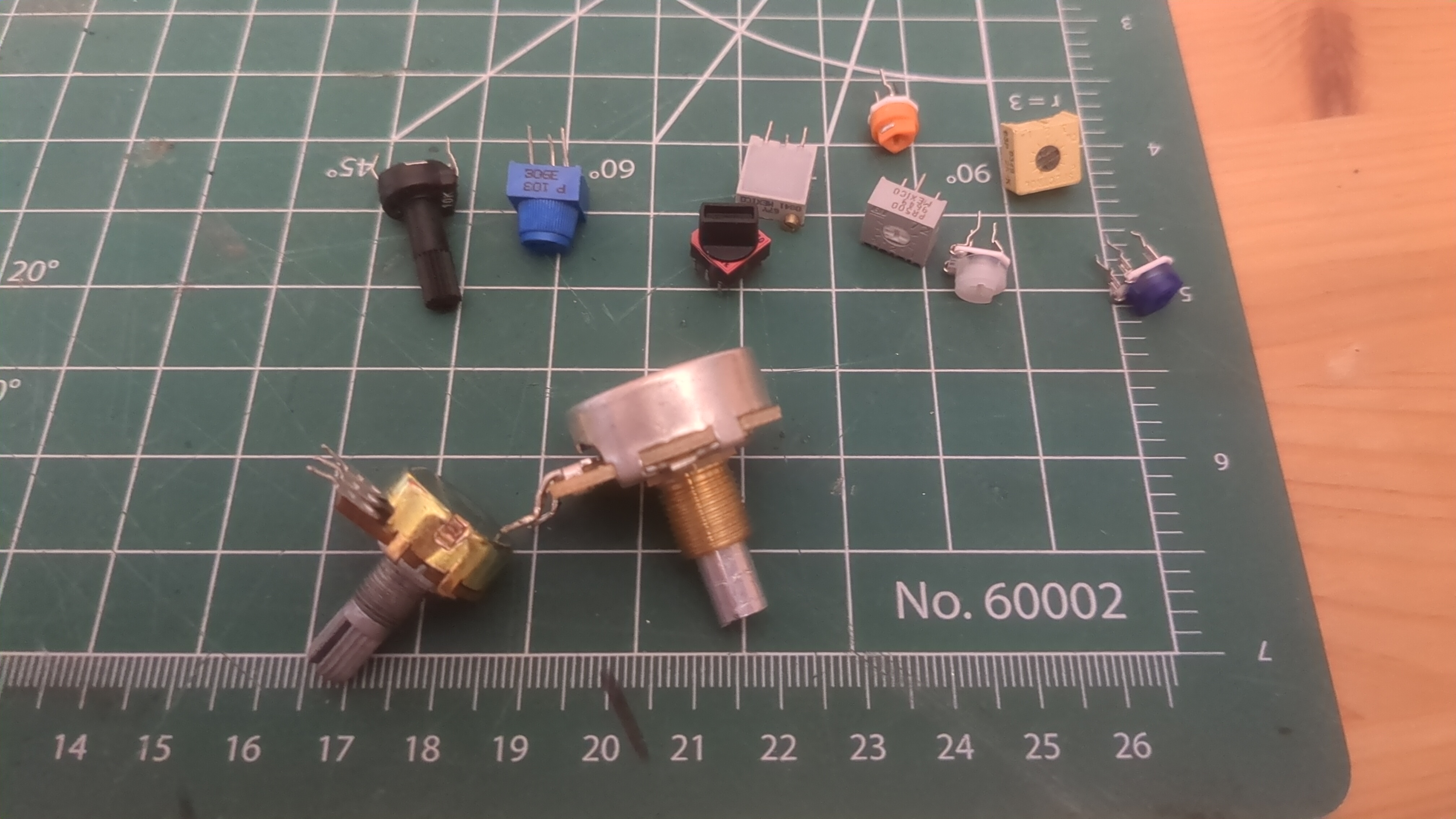
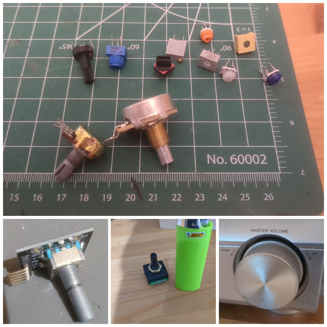
Potentiometers are straightforward in design and well-suited for applications where a high level of precision is not critical. They fall under the category of variable resistors and are characterized by having three terminals:
For the image below
- Low: The lower potential pin should be connected to a constant source near the ground potential
- Wiper: This pin is the variable part which will vary in potential (somewhere between the HIGH and LOW pin depending on where the knob is turned to)
- High: The Higher potential pin which should connect to a constant source above ground potential
Taking Apart a Potentiometer
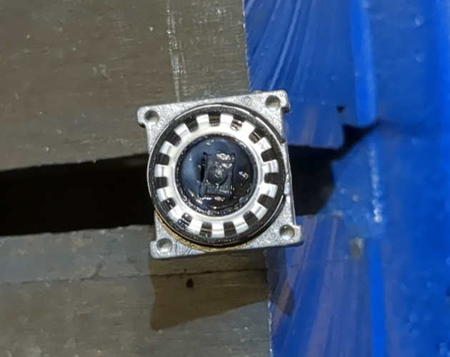
Let's take apart a potentiometer so you can see what's inside:
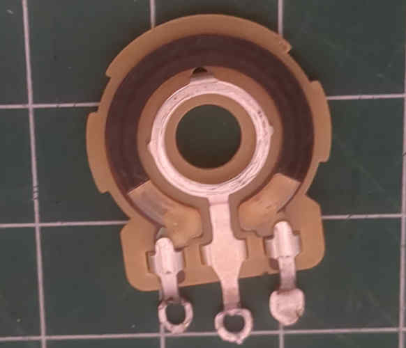
In this image, you can see the resistive ring (the blackish ring between the two outer pins) made out of a semi-conductive material (in this case carbon). The wiper (middle pin) connects to a lead that drags along this ring, creating a variable resistance between the wiper pin and the external pins.
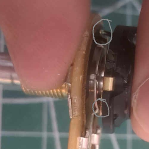
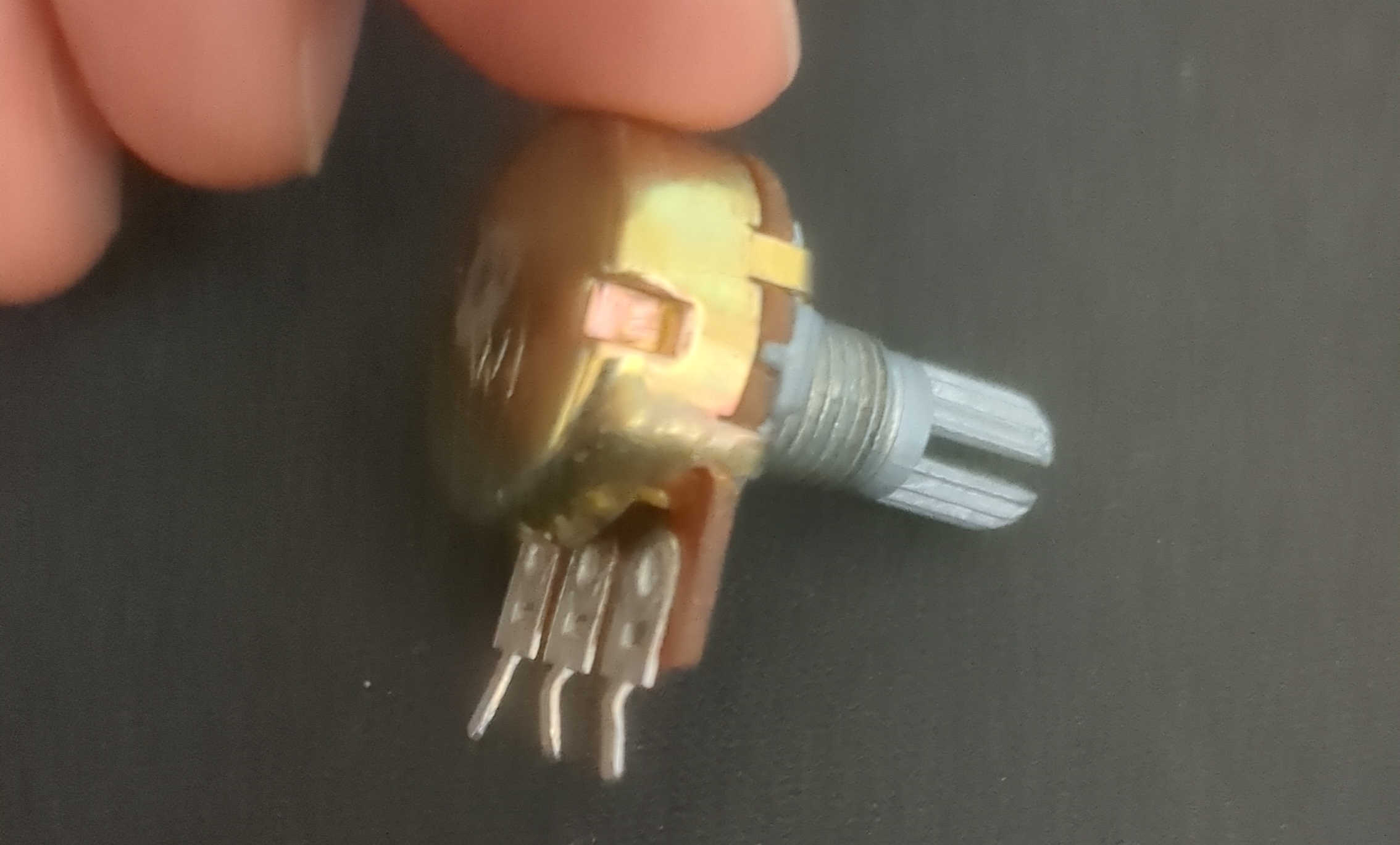
This is a side view of a partially disassembled pot. You can see at the top (circled) that the wiper (gold lead, shown in the last photo) touches the resistive ring. The other lead, which I circled in the lower half, is where the wiper touches the wiper pin (the metallic ring shown in the first photo).
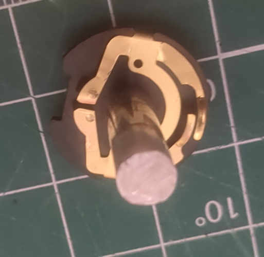
This photo shows the wiper, a highly conductive brass mechanism with springs pressing against the two rings (resistive ring and wiper pin) which connects them all together at different points on the resistive ring creating different resistances at various positions.
The code (Arduino implementations)
Here is the simplest way to use a potentiometer; however, it may not work well depending on your encoder's quality.
// Low pin should connect to the ground
// Wiper will connect to A0
// High PIN has a few options. It needs to be connected to a higher potential than a Low pin. I connected it to 3.3v

void setup() {
 Serial.begin(9600);
}

void loop() {
 // Read the input on analog pin 0 (where the potentiometer is connected):
 int sensorValue = analogRead(A0);

 Serial.println(sensorValue);

 // Convert the sensor reading from a range of 0-1023 to 0-100:
 int scaledValue = map(sensorValue, 0, 1023, 0, 100);


 // Print out the scaled value to the Serial Monitor:
 Serial.println(scaledValue);


 // Wait for a bit to see the changes more clearly:
 delay(100);
}
Potentiometers can experience jittering caused by bouncing and inconsistencies in the semi-conductive material ring. There are a few solutions:
- Software Debouncing: Introducing delays between readings to avoid any jittering.
- Hardware filtering: Introducing hardware such as resistors or capacitors to filter readings
- Digital Filtering: Low pass filters or moving averages.
Software debouncing
Subtle vibrations occur when the wiper is moved and then halted, leading to fluctuations in resistance. This issue can be effectively addressed by introducing delays in the system:
const int potPin = A0; // Potentiometer connected to analog pin A0
int lastPotValue = 0;  // Variable to store the last potentiometer value
int potValue = 0;      // Variable to store the current potentiometer value
int debounceDelay = 50; // Debounce time in milliseconds

void setup() {
 Serial.begin(9600);
}

void loop() {
 int reading = analogRead(potPin);

 // Check if the potentiometer reading is different from the last reading
 if (abs(reading - lastPotValue) > 5) {
 // If the reading is different, reset the debouncing timer
 lastPotValue = reading;
 delay(debounceDelay);
 }

 // Take a new reading after the debounce period
 potValue = analogRead(potPin);

 // Print the stable value to the Serial Monitor
 Serial.println(potValue);

 // Small delay to prevent flooding the serial output
 delay(100);
}
The overall effect is a more stable output. You can adjust and tune the delay to whatever you deem best fit for your hardware.
Note
If you are more advanced with Arduino and C, you may already appreciate interrupts and their benefits. This debouncing technique is also possible with interrupts by storing the time taken at the reading in a global variable and checking if the delay has elapsed.
Hardware Filtering
This is beyond the scope of this post, but I will mention that in addition to high-quality potentiometers, you can also consider adding:
- Hardware low pass filter using a capacitance
- Additional shielding and grounding
Digital Filtering
Here, we are going to implement a simple type of Low-pass filter known as a moving average.
Where:
: Simple Moving Average at time . This represents the average value of the series over a specific number of periods up to time .
: The number of periods over which the average is calculated. This determines the 'window' size of the moving average and affects how responsive the SMA is to changes in the data.
: The value of the series at time . In this case a sam[ple from the pot.
const int potPin = A0; // Potentiometer connected to analog pin A0
const int numReadings = 10; // Number of readings to average
int readings[numReadings]; // Array to store the readings
int readIndex = 0; // Index of the current reading
int total = 0; // Running total of the readings
int average = 0; // Average of the readings

void setup() {
 Serial.begin(9600);

 // Initialize all the readings to 0:
 for (int thisReading = 0; thisReading < numReadings; thisReading++) {
 readings[thisReading] = 0;
 }
}

void loop() {
 // Subtract the last reading:
 total = total - readings[readIndex];

 // Read from the sensor:
 readings[readIndex] = analogRead(potPin);

 // Add this reading to the total:
 total = total + readings[readIndex];

 // Advance to the next position in the array:
 readIndex = readIndex + 1;

 // If we're at the end of the array, wrap around to the beginning:
 if (readIndex >= numReadings) {
 readIndex = 0;
 }

 // Calculate the average:
 average = total / numReadings;

 // Send the average to the computer:
 Serial.println(average);

 // Delay a bit to keep the serial output readable:
 delay(100);
}
Warning
You should tune the number of samples, balancing the responsiveness and improvement of Jitter.
This method combined with the debouncingwill significantly improve the most straightforward method.
EMA Filter
Another filter you can implement is an Exponential Moving Average (EMA). This gives more weight to recent data points, making it more responsive to new information.
Where:
Where: is the Exponential Moving Average at time .
is the smoothing factor, calculated as , where is the number of periods.
is the value of the data series at time .
is the EMA value of the previous period.
Simple Average
Yet another filtering technique is a simple average. In this case rather than sample the pot once each iteration, you would collect multiple samples at each iteration to improve the reading quality. This comes at the price of being much slower (if each read takes 5ms, 5 samples would make each read take > 25ms), but offers improved performance and can even be combined with SMA or EMA.
Where:
is the total number of data points in the series.
is the value of the data series at the -th position.
Extremes
Potentiometers have a notable limitation in their response curve, especially noticeable at the beginning and end of their range. This issue arises from their construction and operational principles. The resistive elements in potentiometers, made from carbon, ceramic-metal compounds, and conductive plastics, are similar to those used in resistors. As the wiper slides over this resistive path, it alters the resistance between the wiper and the high and/or low connection points. While this mechanism functions effectively around the middle of the resistive path, minor movements can cause substantial variations in output at the extreme ends. This results in a lack of precision and is often manifested as sudden jumps in value at these extreme positions. Such behavior is disadvantageous in scenarios where uniform and smooth control is required across the entire movement range. Introducing thresholds at the extremes to ignore changes in the potentiometer.
Thresholds
const int potPin = A0; // Potentiometer connected to A0
const int lowerThreshold = 200; // Lower threshold value
const int upperThreshold = 800; // Upper threshold value
const int minValue = 0; // Minimum output value
const int maxValue = 100; // Maximum output value

void setup() {
 Serial.begin(9600);
}

void loop() {
 int potValue = analogRead(potPin); // Read the potentiometer
 int outputValue;

 if (potValue < lowerThreshold) {
 outputValue = minValue; // Set to minimum if below the lower threshold
 } else if (potValue > upperThreshold) {
 outputValue = maxValue; // Set to maximum if above the upper threshold
 } else {
 // Scale the value between the thresholds
 outputValue = map(potValue, lowerThreshold, upperThreshold, minValue, maxValue);
 }

 Serial.println(outputValue); // Print the output value
 delay(100); // Short delay for readability
}
Since the worst of the Jitter is at the extremes (highest or lowest positions), this method also helps eliminate most issues.
In conclusion, you should be able to use all of this advice and produce a potentiometer that is much more stable than the default simple way of doing it.
Encoders
While potentiometers are preferred for their simplicity, encoders are much more precise.
There are two different types of encoders:
- Incremental Encoders: Provide relative position information by outputting a series of pulses as they rotate. They typically have two output channels (A and B) that produce square wave pulses in a quadrature-encoded pattern, which allows for detecting the direction of rotation.
- Absolute Encoders: Provide absolute position information for each rotation angle. Each position is uniquely coded, typically using binary or Gray code, which can be read through parallel or serial communication.
There are a few different hardware implementations for encoders:
- Hall Effect Encoders: These use Hall effect sensors to detect magnetic fields generated by a rotating magnet.
- Optical Encoders: Use light passing through a coded disk to detect rotation. Absolute types read the unique patterns for each position, which might involve complex decoding algorithms.
- Magnetic Encoders: Similar to Hall effect encoders, they use magnetic fields but often with different sensor arrangements.
- Mechanical Encoders: Cheap and simple, often used in DIY projects and marketed to Arduino users.
Taking apart a simple Incremental/ Mechanical Encoder
On this side of the encode, you can see a ring with little metal leeds sticking out in a regular pattern. In a moment, we will discuss the quadrate-encoded pattern. For now, understand it mechanically.
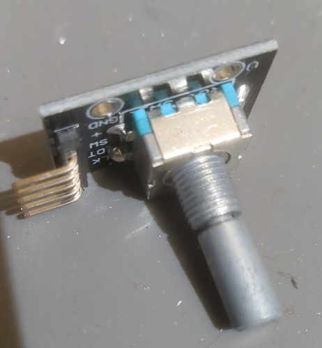
On this side, you can see a few spring-loaded leads (circled in grey) similar to the wiper on the potentiometer. The flap-looking object in the center is just a regular push-button as this encoder features a push button when pressing into the knob.
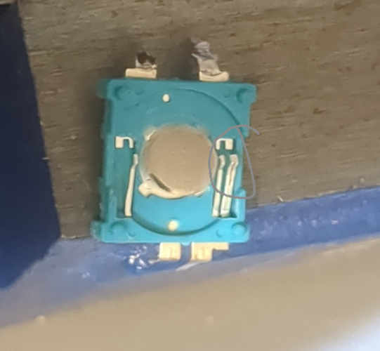
Note
N.b. I broke one pin coming off the device when i desoldered it from a breakout board. It would normally have a total of 5 pins, and two springs on each prong.
Incremental encoders
First, we need to understand the quadrature-encoded pattern.
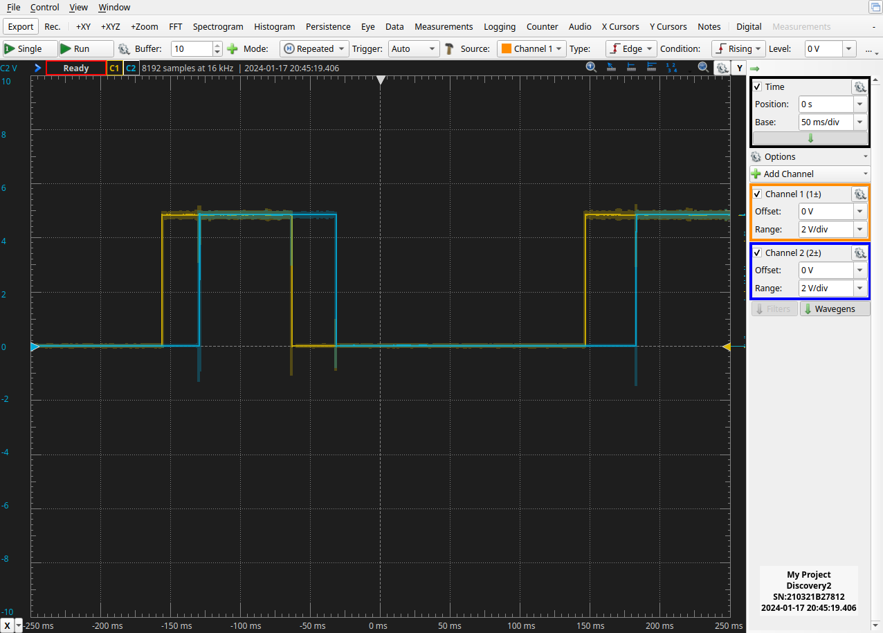
Let's start with some experiential data here's my setup using the Oscilloscope (diligent Discovery 2).
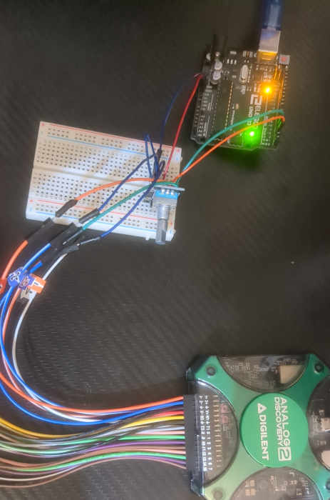
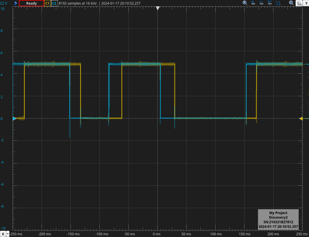
You can see the quadrature-encoded signal after turning the dial clockwise and capturing a few frames.
Here is a table of the various ways to indicate which way the encoder is rotating
| Step | Signal A | Signal B | Direction |
|---|---|---|---|
| 1 | 0 | 0 | Clockwise |
| 2 | 1 | 0 | Clockwise |
| 3 | 1 | 1 | Clockwise |
| 4 | 0 | 1 | Clockwise |
| 1 | 0 | 0 | Counterclockwise |
| 4 | 0 | 1 | Counterclockwise |
| 3 | 1 | 1 | Counterclockwise |
| 2 | 1 | 0 | Counterclockwise |
Looking back to the captured data above, I was turning the encoder clockwise, so let's break it down starting at the -200ms point.
The blue line (signal A) is high as is the orange line (signal B). This corresponds to step 3 in our chart, showing both signals as high (1,1). Next, A falls first, leading to step 4 (0,1). Then, B falls, indicating step 1 (0,0). Following this, A rises, moving to step 2 (1,0). As this pattern continues while I turn the knob clockwise, each step is repeated successively.
Now let's look at counter-clockwise:
In this case, we have the exact opposite. We start at the point -100ms, where both Signal A and Signal B are at a high potential, corresponding to step 3 (1,1). This time, B falls first, transitioning to step 2 (1,0). Next, A falls, indicating step 1 (0,0). Then, B rises, moving to step 4 (0,1). The process continues in this manner.
Here is the pseudo-code for determining the direction of the rotary encoder:
Initialize previousA = 0, previousB = 0
Initialize currentA, currentB

Function readEncoder:
 currentA = Read signal A (as binary 0 or 1) // in an actual application would be handled by interrupts
 currentB = Read signal B (as binary 0 or 1)

 If (previousA == 0 and previousB == 0):
 If (currentA == 1):
 Direction = Clockwise
 Else If (currentB == 1):
 Direction = Counterclockwise

 Else If (previousA == 1 and previousB == 0):
 If (currentB == 1):
 Direction = Clockwise
 Else If (currentA == 0):
 Direction = Counterclockwise

 Else If (previousA == 1 and previousB == 1):
 If (currentA == 0):
 Direction = Clockwise
 Else If (currentB == 0):
 Direction = Counterclockwise

 Else If (previousA == 0 and previousB == 1):
 If (currentB == 0):
 Direction = Clockwise
 Else If (currentA == 1):
 Direction = Counterclockwise

 previousA = currentA
 previousB = currentB

 Return Direction
Arduino Code for Mechanical Encoder
Though the pseudo code above works theoretically, it does not work on an Arduino with a mechanical encoder. Instead, this is by far the best method I could find. It was a learning experience for me as the debouncing method was not the most intuitive, but it performed well. My intuition told me that setting up interrupts to listen for changes in each signal and then determining the direction in the loop would work best. However, reacting to the signal every time it changes poses multiple issues and hardware constraints. Alternatively, this code handles double counting and debouncing nicely. It avoids double counting (mechanical encoders send two pulses per increment) by reacting only when the signal A line goes high and debounces by only checking specific transitions of Signal A, reducing the likelihood of noise or small fluctuations causing false counts.
// Rotary Encoder Inputs
#define PIN_A 2
#define PIN_B 3

volatile int counter = 0; // Counter for the encoder's position
int currentStateA; // Current state of pin A
int lastStateA; // Last state of pin A
bool cw = true; // true indicates CW (Clockwise), false indicates CCW (Counter-Clockwise)

volatile bool updateRequired = false; // Flag to indicate an update is required

void setup() {
 pinMode(PIN_A, INPUT);
 pinMode(PIN_B, INPUT);

 // Setup Serial Monitor
 Serial.begin(9600);

 // Read and store the initial state of PIN_A
 lastStateA = digitalRead(PIN_A);

 attachInterrupt(digitalPinToInterrupt(PIN_A), updateEncoder, CHANGE);
 attachInterrupt(digitalPinToInterrupt(PIN_B), updateEncoder, CHANGE);
}

void loop() {

 if (updateRequired) {
 updateRequired = false;
 String direction = (cw) ? "CW" : "CCW";
 Serial.println(direction);
 }
}

void updateEncoder() {

 currentStateA = digitalRead(PIN_A);

 // Check for state change in PIN_A to avoid double count
 if (currentStateA != lastStateA && currentStateA == HIGH) {

 // Determine rotation direction based on states of PIN_A and PIN_B
 cw = (digitalRead(PIN_B) != currentStateA);

 updateRequired = true;
 }

 lastStateA = currentStateA;
}
Absolute Encoders
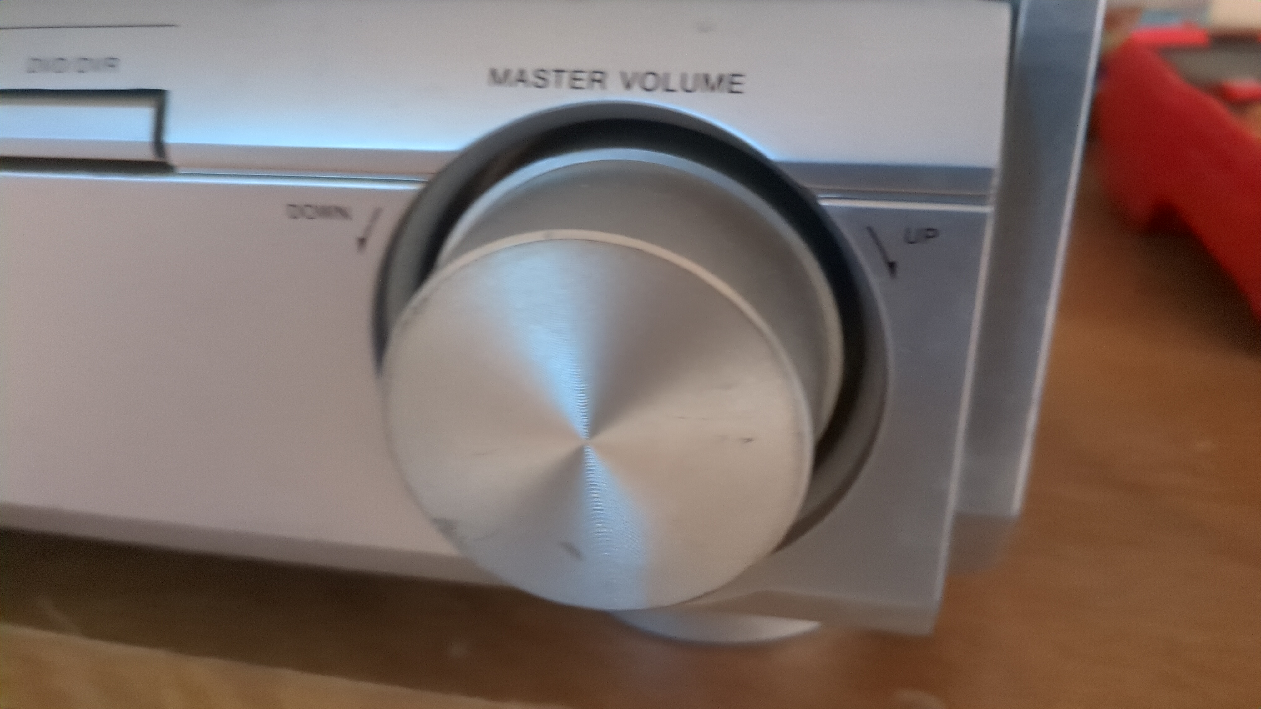
Now for a more interesting type of encoder, the absolute encoder. This encoder is special because it behaves more like a potentiometer in that it always knows its exact position, unlike incremental encoders which can only tell you which direction it was rotated. There are a few ways to source these, as you can find them in amplifiers/stereo systems (commonly the volume knobs), but since I didn’t have a stereo I want to take apart, I got the relatively inexpensive Bourns EAW0J-B24-AE0128.
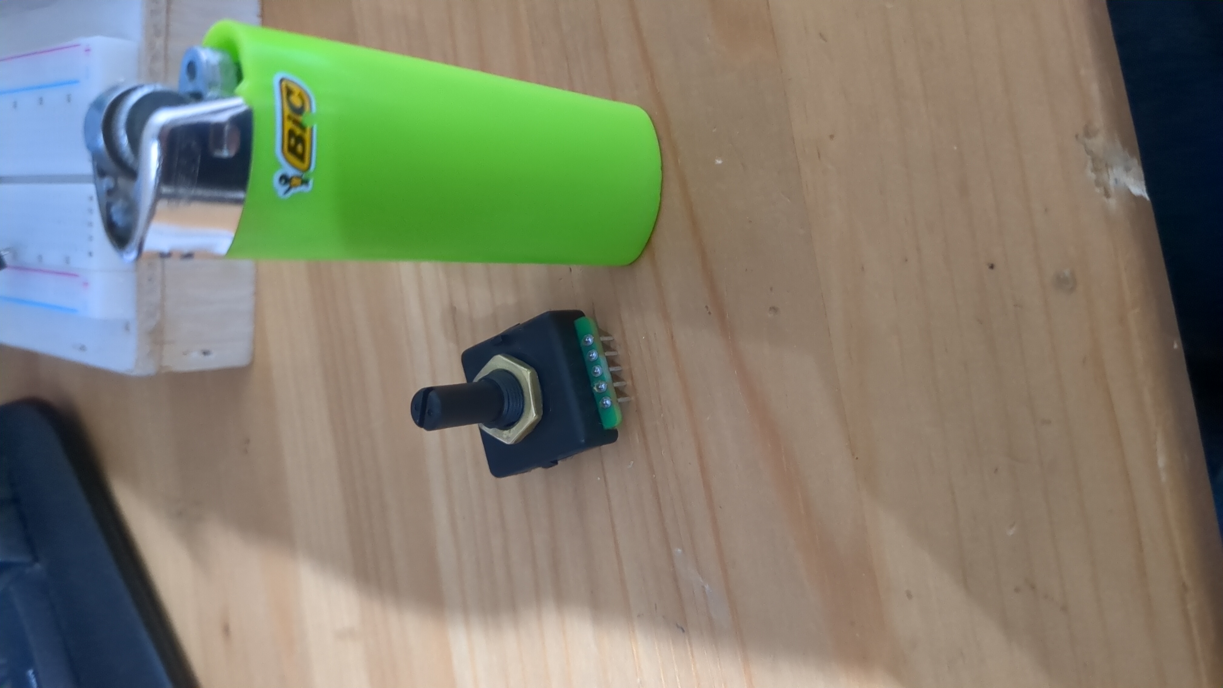
This encoder is great for electronics projects on a budget since it's one of the most cost-effective choices. It works similarly to the incremental encoder with small spring leads that brush against contacts. When the leads are connected (internally in the encoder) it pulls the pins to the common (GND) otherwise the data pins are pulled high with a 4.7KOhm resister. There’s a total of 8 pins which encode each position. Unfortunately, due to what I assume is layout practicallities this doesn’t line up perfectly such that position 0 is 0b2, 1 is 1b2, 2 is 10b2, and so on. Instead, the positions are complex and require a lookup table. For example, position 0 is 127, 1=63,2=62,3=58, etc. Seemingly random but probably due to the best/cost-effective Gray-compatible layout.
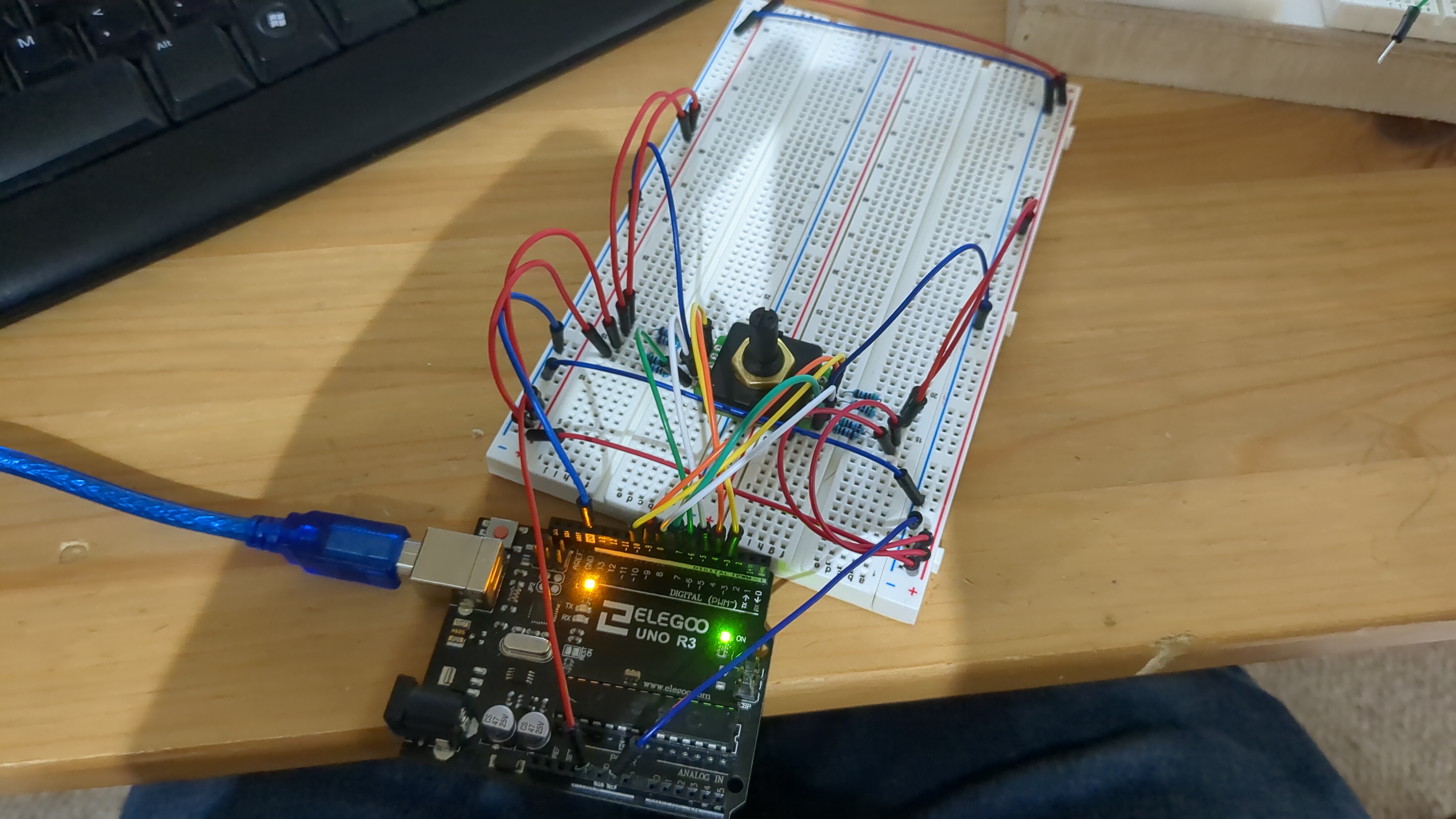
Here's my setup:
First I had to use some shell script chatGPT to extract the numbers from the datasheet and format them as an array.
127,63,62,58,56,184,152,24,8,72,73,77,79,15,47,175,191,159,31,29,28,92,76,12,4,36,164,166,167,135,151,215,223,207,143,142,14,46,38,6,2,18,82,83,211,195,203,235,239,231,199,71,7,23,19,3,1,9,41,169,233,225,229,245,247,243,227,163,131,139,137,129,128,132,148,212,244,240,242,250,251,249,241,209,193,197,196,192,64,66,74,106,122,120,121,125,253,252,248,232,224,226,98,96,32,33,37,53,61,60,188,190,254,126,124,116,112,113,49,48,16,144,146,154,158,30,94,95Then I made it into a look-up table since i can get time (which doesn't matter too much but is easier to code with).
byte lt[128] = {127,63,62,58,56,184,152,24,8,72,73,77,79,15,47,175,191,159,31,29,28,92,76,12,4,36,164,166,167,135,151,215,223,207,143,142,14,46,38,6,2,18,82,83,211,195,203,235,239,231,199,71,7,23,19,3,1,9,41,169,233,225,229,245,247,243,227,163,131,139,137,129,128,132,148,212,244,240,242,250,251,249,241,209,193,197,196,192,64,66,74,106,122,120,121,125,253,252,248,232,224,226,98,96,32,33,37,53,61,60,188,190,254,126,124,116,112,113,49,48,16,144,146,154,158,30,94,95 };

byte lookup[256];

for( int i = 0; i < 256; i ++ ){
 lookup[i] = -1; //255
}

for( int i =0; i < 128; i++){
 lookup[lt[i]] = i;
}

Serial.print("{ ");
for( int i =0; i < 255; i++){
 Serial.print(lookup[i]);
 Serial.print(" , ");
}
Serial.print(lookup[255]);
Serial.println(" };");
Now we can get the position like this lookup[output_base_10] very quickly.
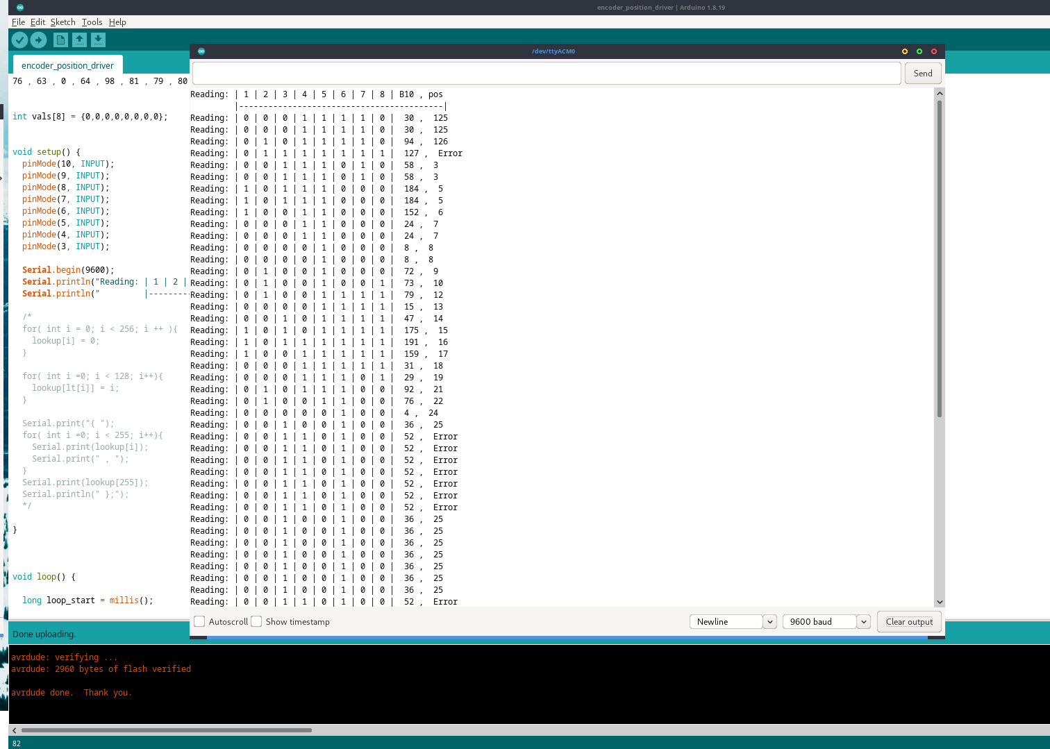
First I tested it using this Arduino script, and after some tinkering, I got some stable outputs with this code.
byte lookup[256] = { 255 , 56 , 40 , 55 , 24 , 255 , 39 , 52 , 8 , 57 , 255 , 255 , 23 , 255 , 36 , 13 , 120 , 255 , 41 , 54 , 255 , 255 , 255 , 53 , 7 , 255 , 255 , 255 , 20 , 19 , 125 , 18 , 104 , 105 , 255 , 255 , 25 , 106 , 38 , 255 , 255 , 58 , 255 , 255 , 255 , 255 , 37 , 14 , 119 , 118 , 255 , 255 , 255 , 107 , 255 , 255 , 4 , 255 , 3 , 255 , 109 , 108 , 2 , 1 , 88 , 255 , 89 , 255 , 255 , 255 , 255 , 51 , 9 , 10 , 90 , 255 , 22 , 11 , 255 , 12 , 255 , 255 , 42 , 43 , 255 , 255 , 255 , 255 , 255 , 255 , 255 , 255 , 21 , 255 , 126 , 127 , 103 , 255 , 102 , 255 , 255 , 255 , 255 , 255 , 255 , 255 , 91 , 255 , 255 , 255 , 255 , 255 , 116 , 117 , 255 , 255 , 115 , 255 , 255 , 255 , 93 , 94 , 92 , 255 , 114 , 95 , 113 , 0 , 72 , 71 , 255 , 68 , 73 , 255 , 255 , 29 , 255 , 70 , 255 , 69 , 255 , 255 , 35 , 34 , 121 , 255 , 122 , 255 , 74 , 255 , 255 , 30 , 6 , 255 , 123 , 255 , 255 , 255 , 124 , 17 , 255 , 255 , 255 , 67 , 26 , 255 , 27 , 28 , 255 , 59 , 255 , 255 , 255 , 255 , 255 , 15 , 255 , 255 , 255 , 255 , 255 , 255 , 255 , 255 , 5 , 255 , 255 , 255 , 110 , 255 , 111 , 16 , 87 , 84 , 255 , 45 , 86 , 85 , 255 , 50 , 255 , 255 , 255 , 46 , 255 , 255 , 255 , 33 , 255 , 83 , 255 , 44 , 75 , 255 , 255 , 31 , 255 , 255 , 255 , 255 , 255 , 255 , 255 , 32 , 100 , 61 , 101 , 66 , 255 , 62 , 255 , 49 , 99 , 60 , 255 , 47 , 255 , 255 , 255 , 48 , 77 , 82 , 78 , 65 , 76 , 63 , 255 , 64 , 98 , 81 , 79 , 80 , 97 , 96 , 112 , 255 };

int vals[8] = {0,0,0,0,0,0,0,0};

void setup() {
 pinMode(10, INPUT);
 pinMode(9, INPUT);
 pinMode(8, INPUT);
 pinMode(7, INPUT);
 pinMode(6, INPUT);
 pinMode(5, INPUT);
 pinMode(4, INPUT);
 pinMode(3, INPUT);

 Serial.begin(9600);
 Serial.println("Reading: | 1 | 2 | 3 | 4 | 5 | 6 | 7 | 8 | B10 , pos ");
 Serial.println("         |---------------------------------------------|");
}

void loop() {

 for( int i = 0; i < 8; i++){
 vals[i] = digitalRead(i+3);
 }

 Serial.print("Reading:");
 for( int i =7; i >= 0; i-- ){
 Serial.print(" | ");
 Serial.print(vals[i]);
 }
 Serial.print(" |  ");

 int num = 0;
 for( int i = 0; i < 8; i++){
 num |= (vals[i] << i);
 }
 Serial.print(num);
 Serial.print(" ,  ");

 if(lookup[num] >= 0){
 Serial.println(lookup[num]);
 }else{
 Serial.println("Error");
 }
}
Warning
to get stable outputs I had to apply downward force on the encoder with all the breadboards I had available to get good connections. Those errors for 52 are caused by loose connections This shouldn’t be an issue for soldering to a custom PCB but is worth noting if you’re getting lots of errors.
Note
The other error was caused because I was originally using 0 to represent no match, but that didn't work because I had a position 0. So i just changed that to -1(255 since it's stored in byte) and now it works perfectly. The code was updated the image was not.
Now for error checking because if the connections are loose there can easily be a lost digit. Since this is gray code we can check if the sequence is gray code. Gray code simply means binary number sequences that change only 1 bit at a time. For example 100 to 110 is valid since only bit 2 changed, but 100 to 010 is invalid since both bit 2 and 3 changed.
byte lookup[256] = { 255 , 56 , 40 , 55 , 24 , 255 , 39 , 52 , 8 , 57 , 255 , 255 , 23 , 255 , 36 , 13 , 120 , 255 , 41 , 54 , 255 , 255 , 255 , 53 , 7 , 255 , 255 , 255 , 20 , 19 , 125 , 18 , 104 , 105 , 255 , 255 , 25 , 106 , 38 , 255 , 255 , 58 , 255 , 255 , 255 , 255 , 37 , 14 , 119 , 118 , 255 , 255 , 255 , 107 , 255 , 255 , 4 , 255 , 3 , 255 , 109 , 108 , 2 , 1 , 88 , 255 , 89 , 255 , 255 , 255 , 255 , 51 , 9 , 10 , 90 , 255 , 22 , 11 , 255 , 12 , 255 , 255 , 42 , 43 , 255 , 255 , 255 , 255 , 255 , 255 , 255 , 255 , 21 , 255 , 126 , 127 , 103 , 255 , 102 , 255 , 255 , 255 , 255 , 255 , 255 , 255 , 91 , 255 , 255 , 255 , 255 , 255 , 116 , 117 , 255 , 255 , 115 , 255 , 255 , 255 , 93 , 94 , 92 , 255 , 114 , 95 , 113 , 0 , 72 , 71 , 255 , 68 , 73 , 255 , 255 , 29 , 255 , 70 , 255 , 69 , 255 , 255 , 35 , 34 , 121 , 255 , 122 , 255 , 74 , 255 , 255 , 30 , 6 , 255 , 123 , 255 , 255 , 255 , 124 , 17 , 255 , 255 , 255 , 67 , 26 , 255 , 27 , 28 , 255 , 59 , 255 , 255 , 255 , 255 , 255 , 15 , 255 , 255 , 255 , 255 , 255 , 255 , 255 , 255 , 5 , 255 , 255 , 255 , 110 , 255 , 111 , 16 , 87 , 84 , 255 , 45 , 86 , 85 , 255 , 50 , 255 , 255 , 255 , 46 , 255 , 255 , 255 , 33 , 255 , 83 , 255 , 44 , 75 , 255 , 255 , 31 , 255 , 255 , 255 , 255 , 255 , 255 , 255 , 32 , 100 , 61 , 101 , 66 , 255 , 62 , 255 , 49 , 99 , 60 , 255 , 47 , 255 , 255 , 255 , 48 , 77 , 82 , 78 , 65 , 76 , 63 , 255 , 64 , 98 , 81 , 79 , 80 , 97 , 96 , 112 , 255 };

int vals[2][8] = {{0,0,0,0,0,0,0,0},{0,0,0,0,0,0,0,0}};
int sample = 0;


void setup() {
  pinMode(10, INPUT);
  pinMode(9, INPUT);
  pinMode(8, INPUT);
  pinMode(7, INPUT);
  pinMode(6, INPUT);
  pinMode(5, INPUT);
  pinMode(4, INPUT);
  pinMode(3, INPUT);

 Serial.begin(9600);
 Serial.println("Reading: | 1 | 2 | 3 | 4 | 5 | 6 | 7 | 8 | B10 , pos ");
 Serial.println("         |---------------------------------------------|");
}

bool isGrayCode(int vals[2][8]) {
 for (int i = 0; i < 8; ++i) {
 int diff = vals[0][i] ^ vals[1][i];
 if ((diff & (diff - 1)) != 0) // Check if only one bit is different
 return false;
 }
 return true;
}

void loop() {

 for( int i = 0; i < 8; i++){
 vals[sample][i] = digitalRead(i+3);
 }

 Serial.print("Reading:");
 for( int i =7; i >= 0; i-- ){
 Serial.print(" | ");
 Serial.print(vals[sample][i]);
 }
 Serial.print(" |  ");

 int num = 0;
 for( int i = 0; i < 8; i++){
 num |= (vals[sample][i] << i);
 }
 if(!isGrayCode(vals)){
 Serial.println("GREY ERROR");
 }
 Serial.print(num);
 Serial.print(" ,  ");

 if(lookup[num] >= 0){
 Serial.println(lookup[num]);
 }else{
 Serial.println("Error");
 }

 sample != sample;
}
Unfortunately, this doesn’t work super well for the errors I’m getting since the error is likely to be one pin failing which is still a valid gray code. A more robust error checking is better for a longer distance connection between MCUs where a noisy environment with less reliable transmission. For now, I’m going to leave a more complex error check for a later date if needed in a real-world application that's properly soldered and shielded will perform well with this code.
Conclusion
I covered some basic programming and a little on the hardware side. Hopefully, this gives you some theory, code, and examples to work with. Thanks for reading.