Is Repairing a Cheap CNC Mill Worth It?
About a year ago, I bought this Amazon mill for about 200$ CAD on a local marketplace. I had absolutely no idea if it worked, furthermore, the electronics were in pieces so a bit of a gamble for sure. In this post, I will explain how I got it in working condition and tell you if this type of used equipment (Amazon/Chinese mill, 3D printers, etc) is worth buying.
What exactly Did I Buy?
This was a later picture when I started repairing it. The condition was similar except missing all wiring. The control board was completely disconnected, it didn’t come with a wiring harness or power supply, and it was missing a few other odds and ends like a drag chain. One reason I did decide to buy, was the larger spindle with its power supply (included) on this mill. Ultimately, it seemed like it was in good condition but there was no way of telling if for example, the steppers were working or if the bearings, rails, bushing, lead screws, gantry, and even the base were true and in good condition. I guess I also had no idea about the power supply and even the control board.
So at first, I had no idea what mill it was and where the control board came from. My best guess is that the mill was this Vevor 3040, and the control board was basically an Arduino with Tmc222 steppers. I found a similar one on Amazon.
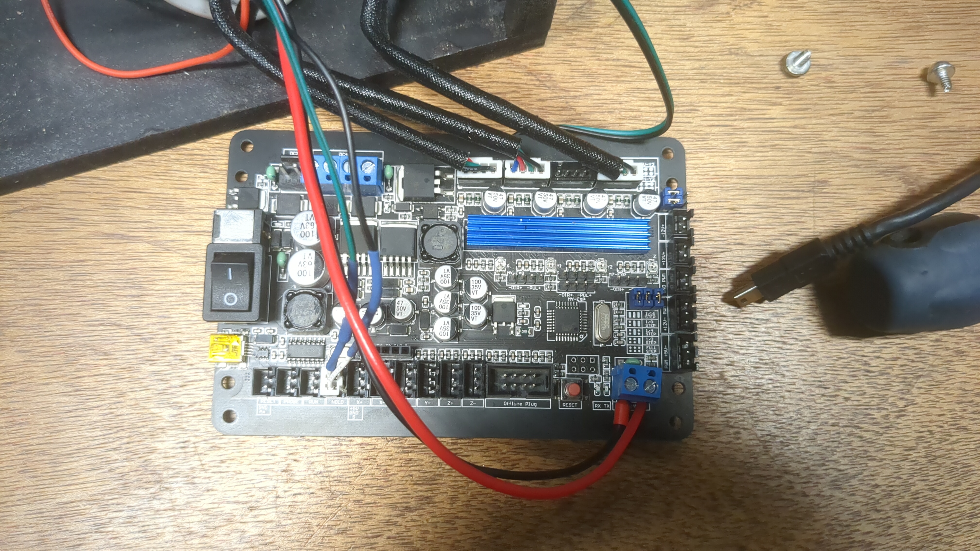
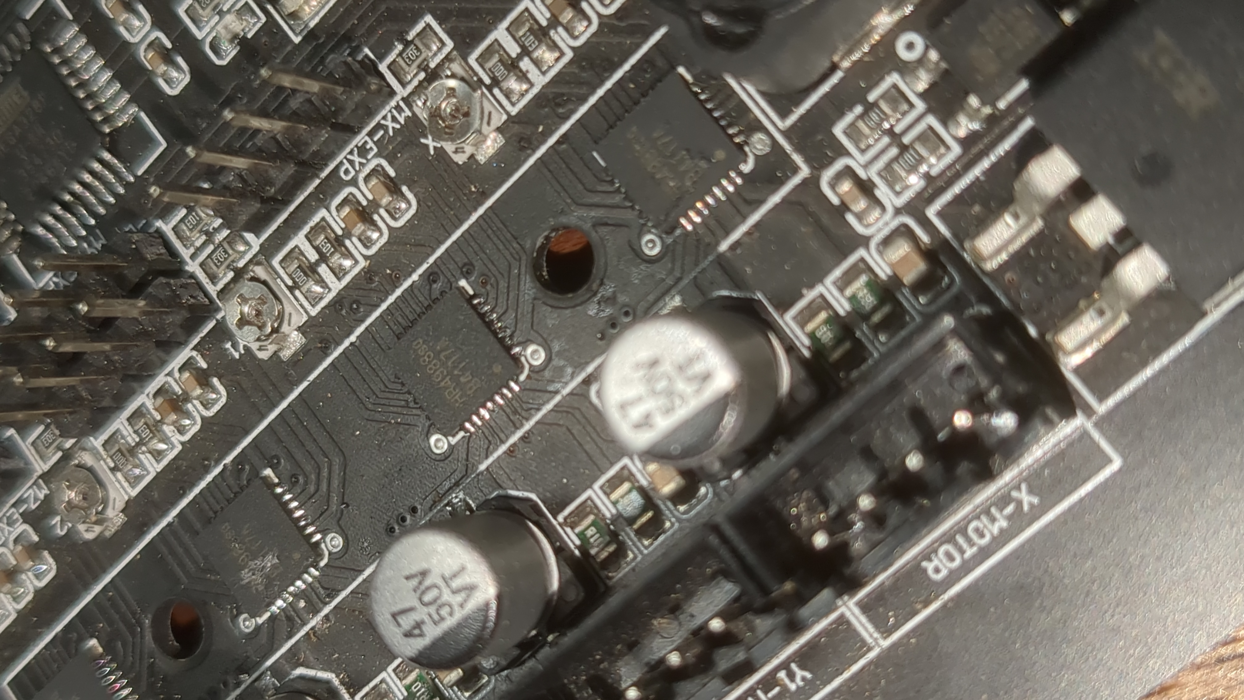
At the time I didn't know anything about these small mills and software ecosystems like GRBL, UGS, and Mach3, so this was all very new to me (in fact, I hadn't even used CAM at this point which is a little more complex to operate than 3D printer slicer software). Luckily the control board is just an Arduino chip with GRBL, it's firmware, which you can update/configure with Arduino Studio, PlatformIO, or even just AVRdude as it works exactly like an Arduino and is programmable with a USB connection via a built-in DUF (easier than say updating Marlin on a 3D printer which loads the firmware from a SDcard).
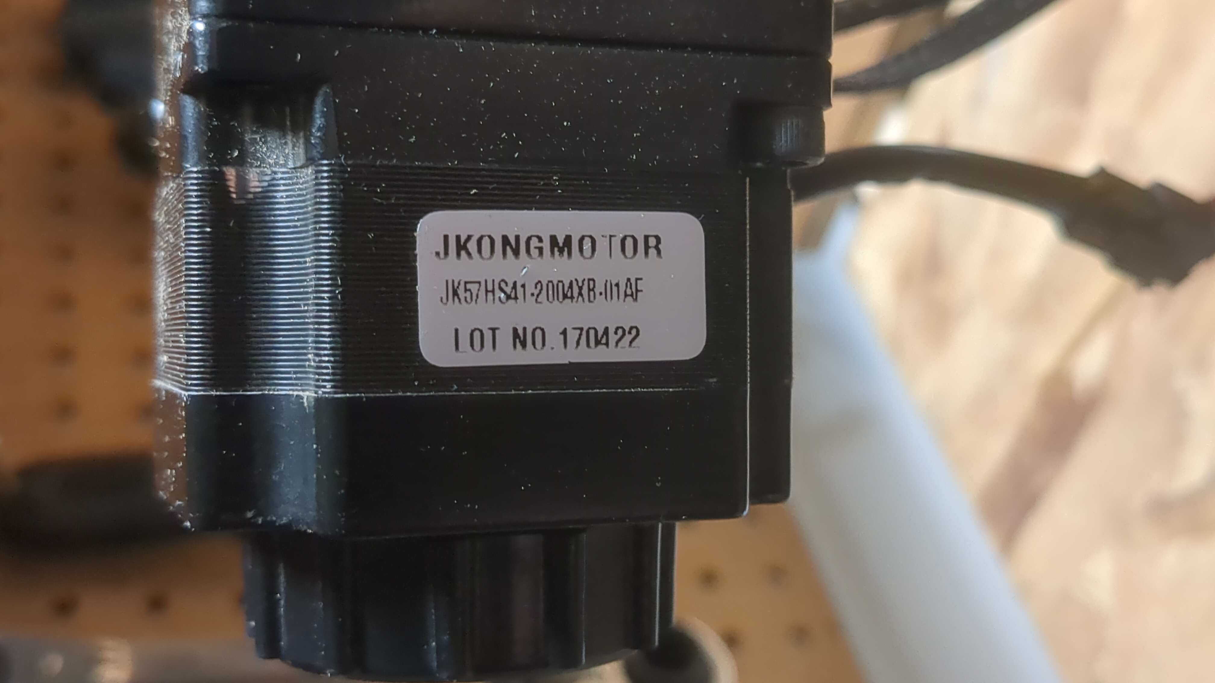
The steppers are Nema 34s with the larger JST-SM (commonly automotive) connectors.
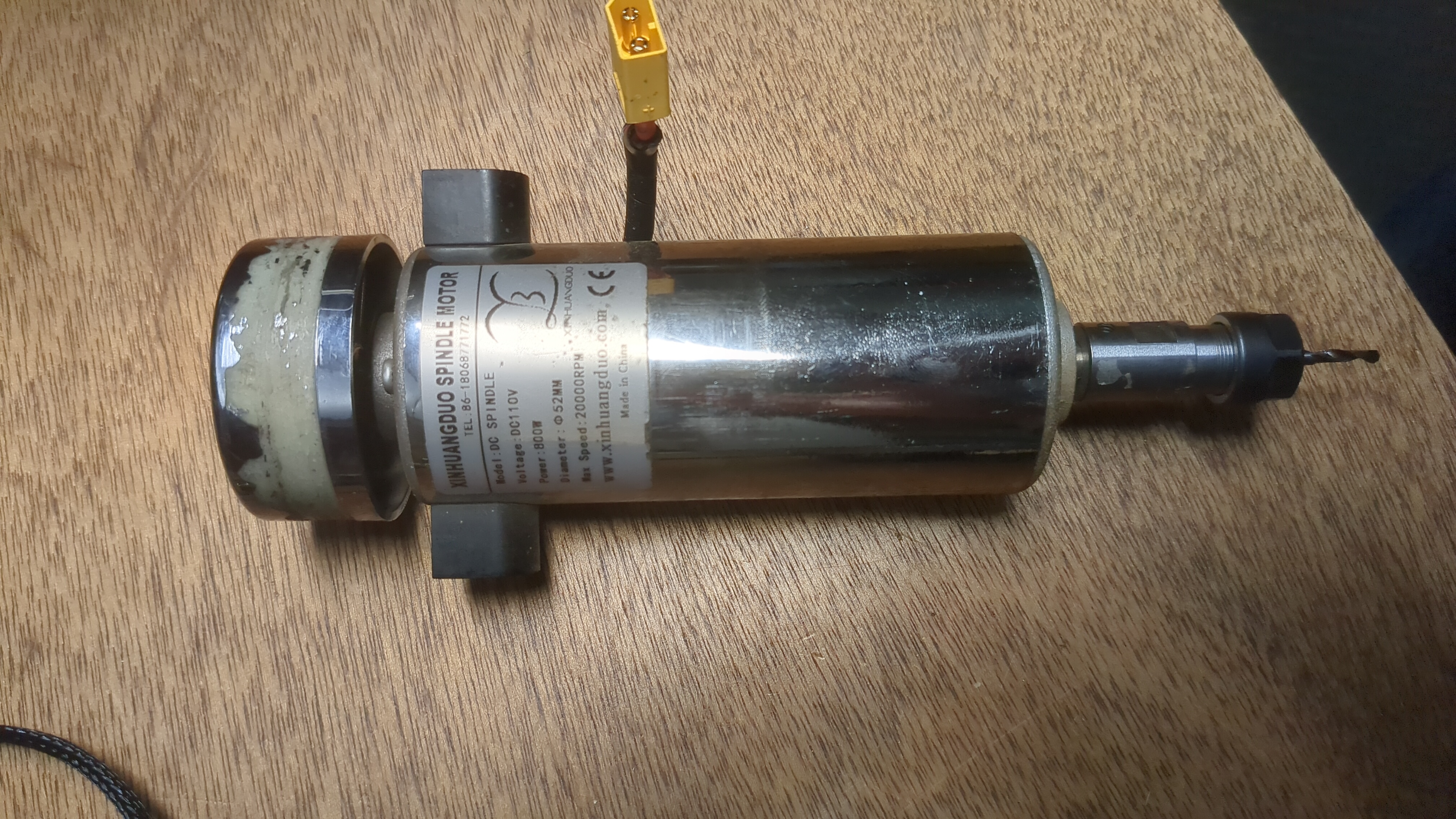
Looking further into the mill itself everything mechanical looks fine after a cleanup. The upgraded spindle appeared to be this Genmitsu Air-Cooled 300W though it has a bit of a different power supply and didn't come with the pot or spare collets.
Although the mill came with no wiring, it did come with some shielded wirings and crimped JST PH connectors on the control board which was great news for this rebuild because shielding here is a must as the high-power spindle will induce a magnetic field that will distort data lines to the steppers.
Getting it Working
First, I cleaned it off with some paper towels and compressed air. I then applied Teflon lube to the lead screws and cleaned them with a toothbrush to get rid of all the debris (aluminum shavings and wood dust).
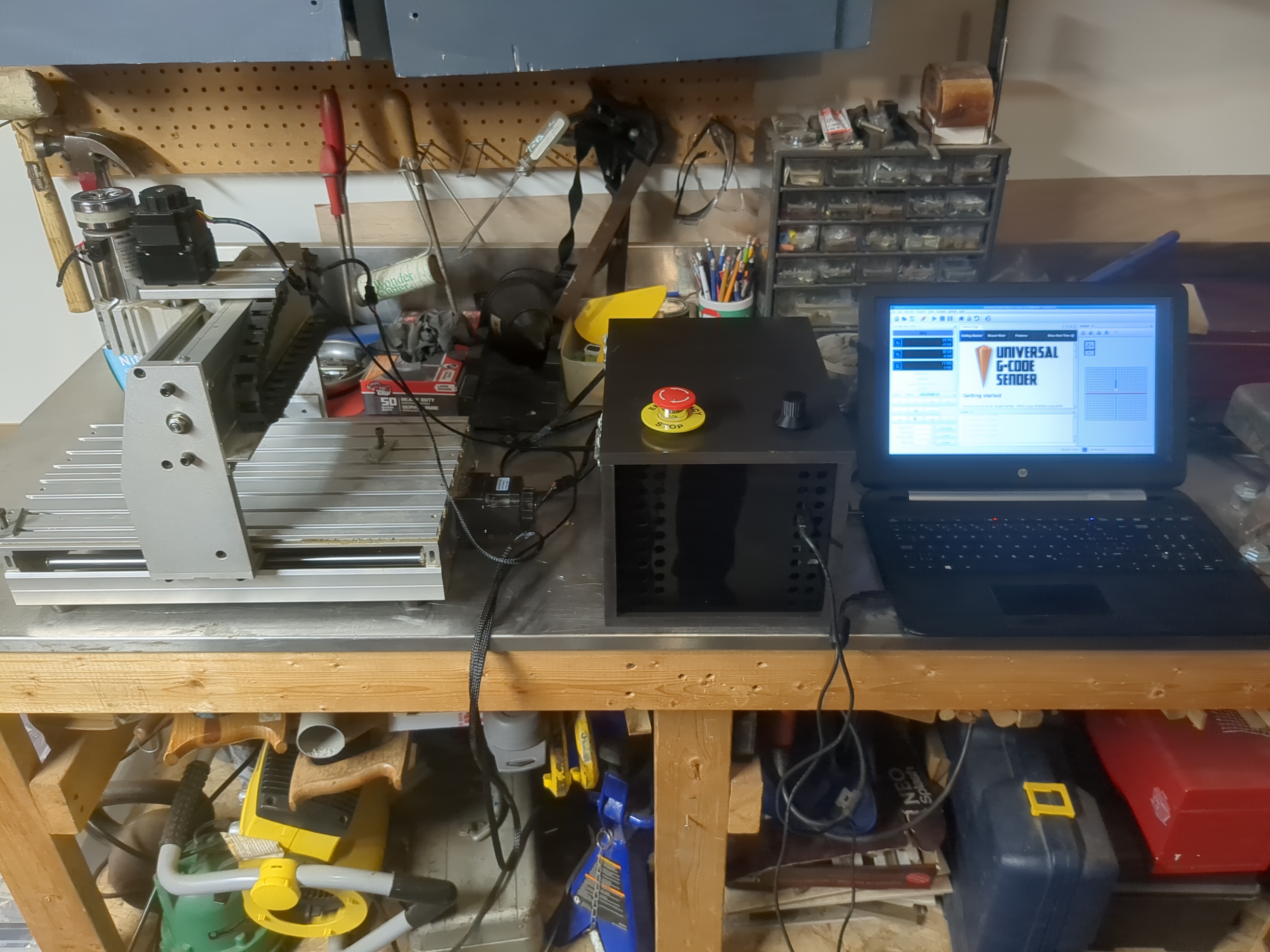
I managed to Wire it all together temporally with a power supply I had on hand. I downloaded UGS (Universal Gcode Sender) after reading it was much simpler than Mach3 and connected my computer running UGS to the mill's control board. To my relief, it worked perfectly. The gantry never stalled or got stuck it just needed a mechanical tune-up and some Teflon lube. No new parts were required other than some wires, switches, knobs, power supply, and an enclosure.
One last thing i had to do was tighten up the lead screw couplers which should be done before each usage anyway.
Building an Electronics Enclosure
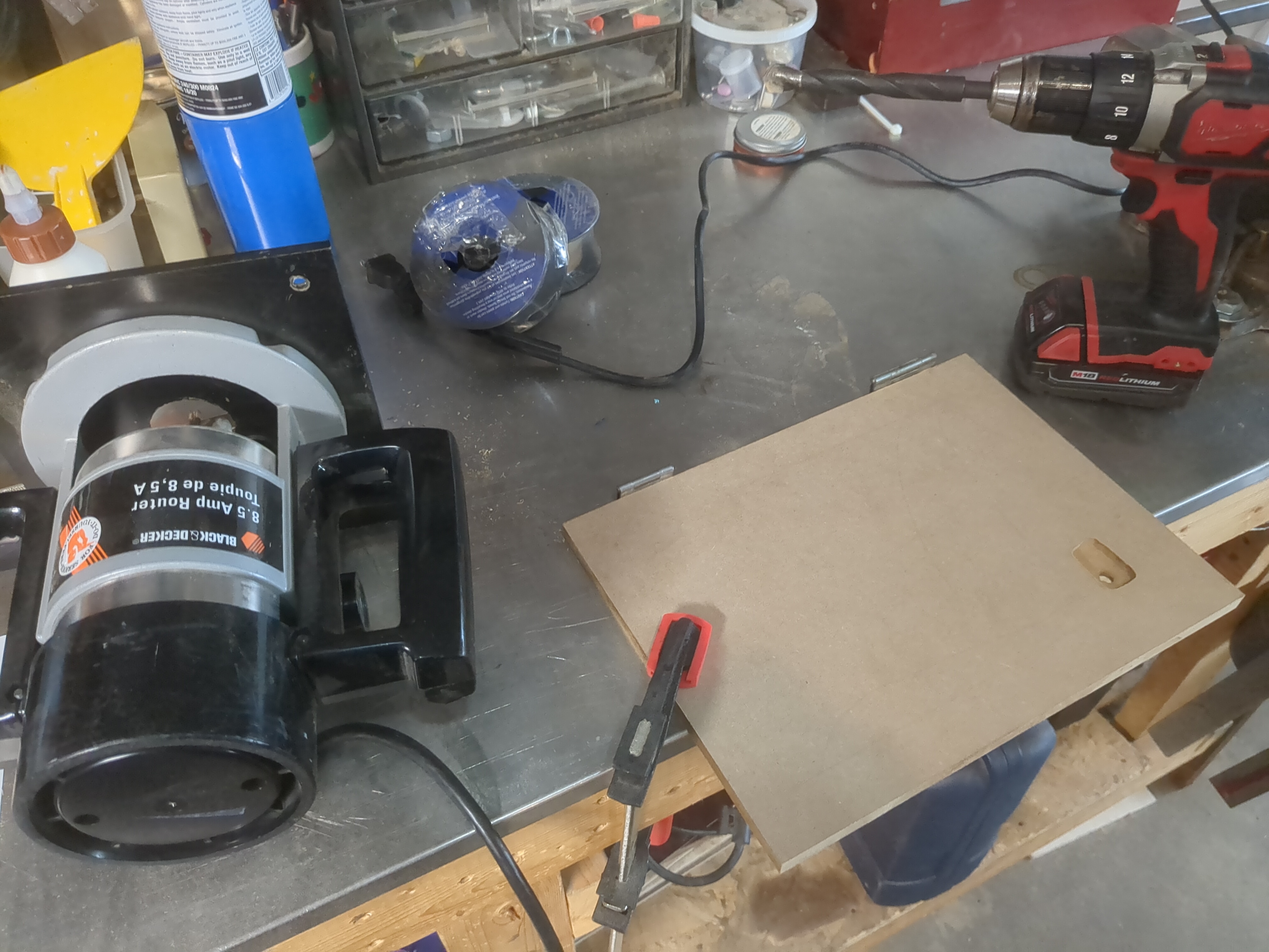
It would be nice to have the original Vivor enclosure as it looks like a decent sheet metal build. One downside is it might not have fit the additional power supply for the upgraded spindle. Since I didn't have the original, the previous owner said he threw it out, I decided to go with a DIY enclosure. I built it using what I had on hand, which was MDF, and I also bought some cheap acrylic sheets to spruce it up a bit. My review of working with MDF is not great as it seems to be cheap, toxic, annoying to clean up, and contrary to popular belief very difficult to machine as it flakes unlike most hardwoods or even plywood which can splinter but often cut away nicely (at the correct rate and with the correct bit).
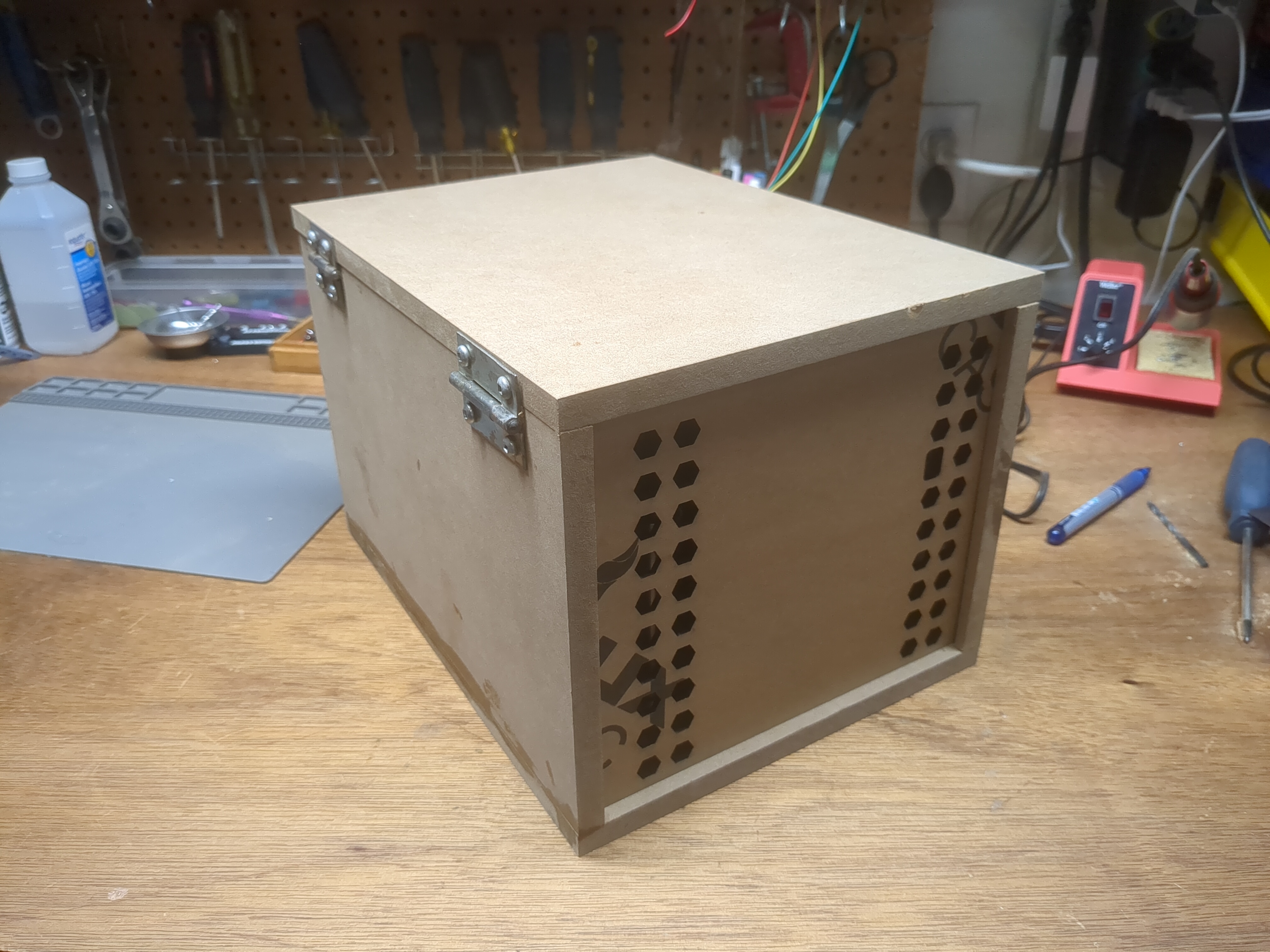
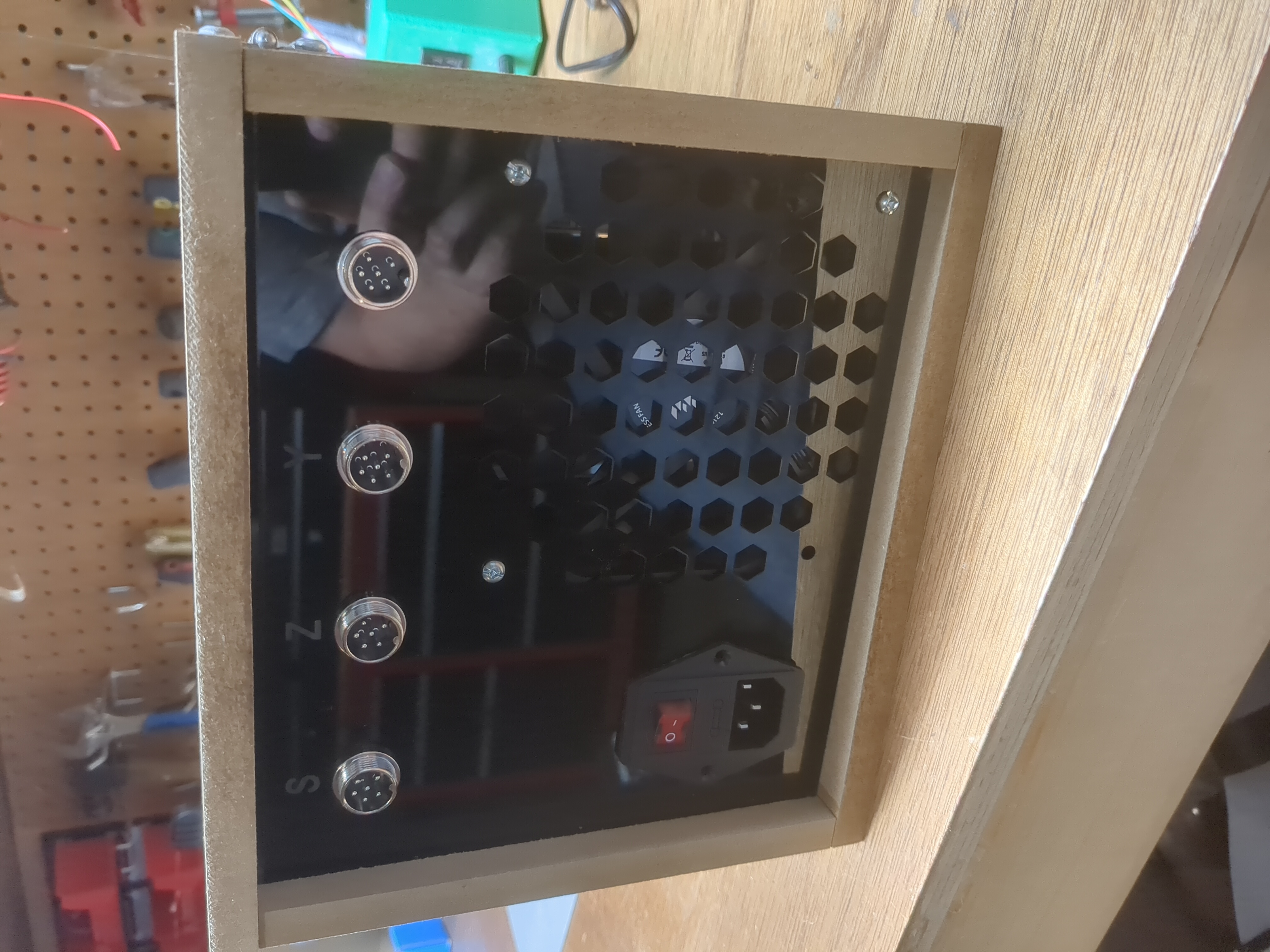
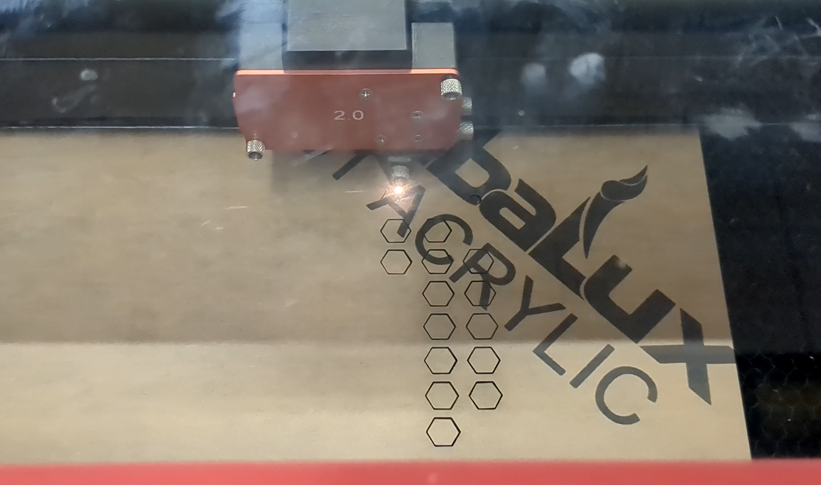
I cut out the MDF sheets with a table saw, and used a hand router to carve some grooves for the acrylic sheets. For the acrylic sheets, I went all out because I had access to a CNC CO2 laser. I cut out a nice pattern for the cooling fan and for each connection with engraved labels for convenience.
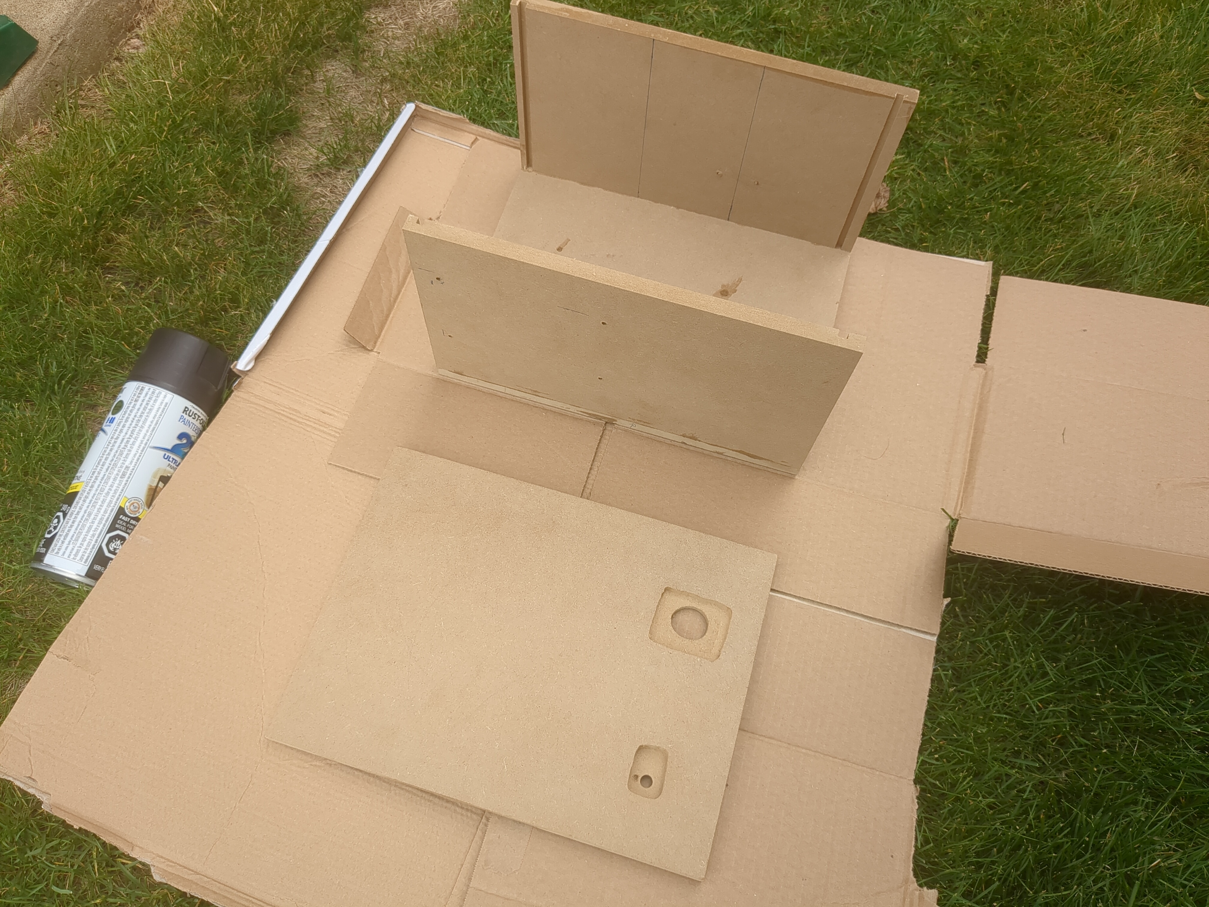
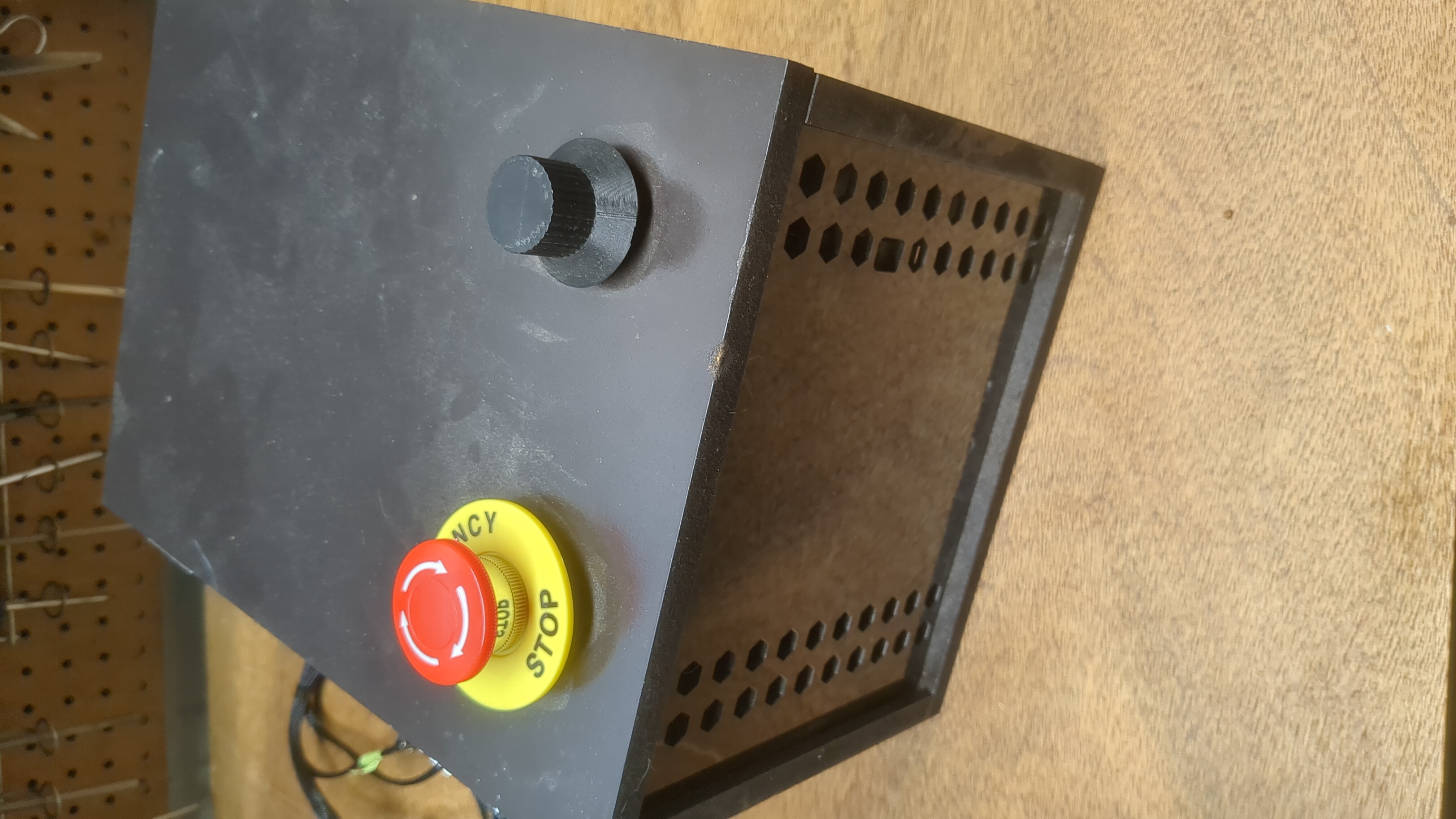
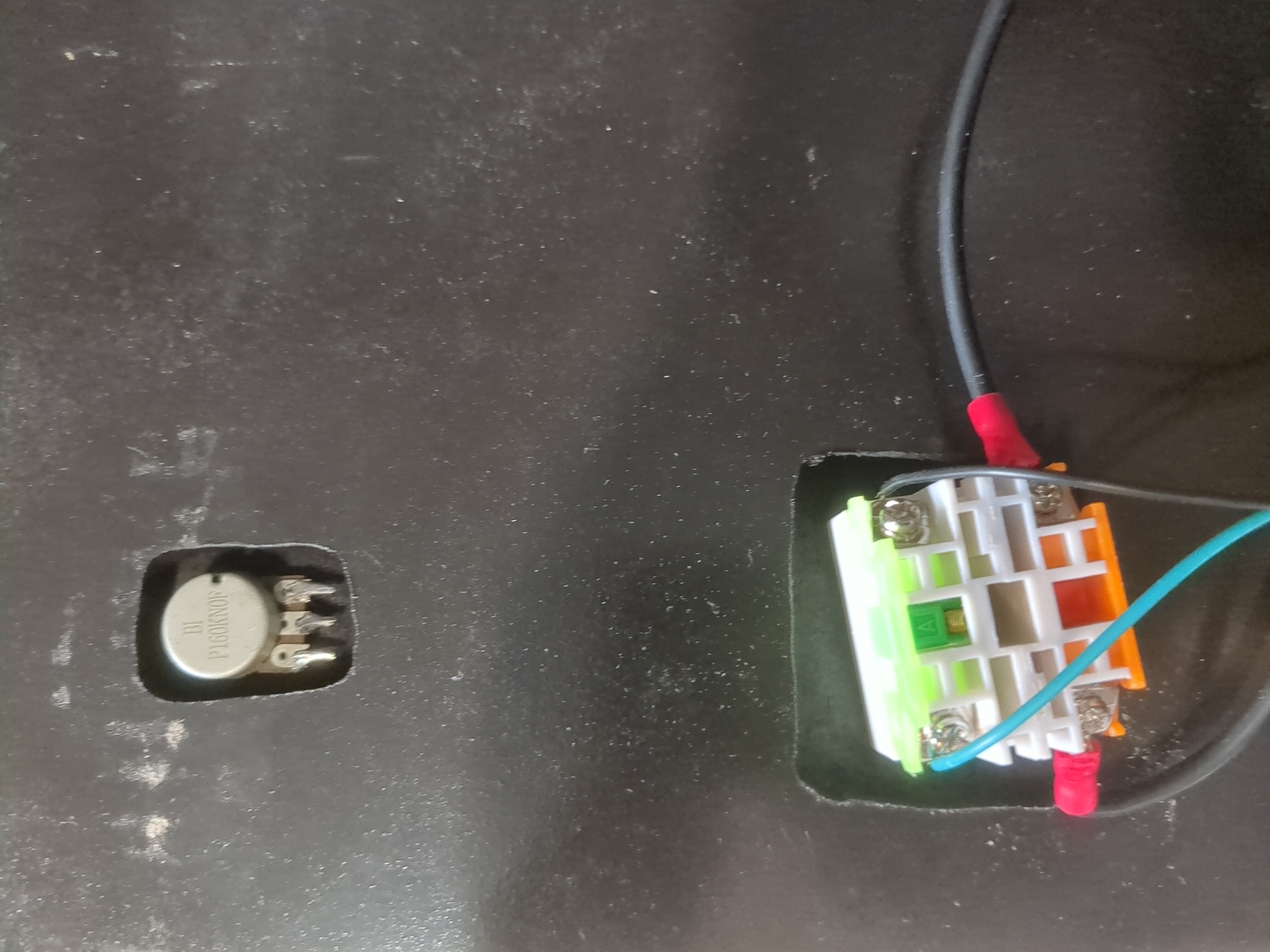
On the top of the enclosure, I used the hand router to mill out an area for the potentiometer and The E- stop switch. The E-stop is an obvious must for operating a mill, the nice thing about this E-stop is it has both a NO (normally open) and NC (normally closed) isolated switch. Both switches are rated for 5A at 250V which adds a lot of versatility for both power and data. Looking back a few things changed in my original plan but I decided to make the NC connection the power for the spindle (so hitting E-stop would cut power to the spindle) and the NO is a 5V signal that goes to the control board and pauses the Gcode, which has proved to be a valuable feature easily stopping and resuming pieces. I just used a random pot I had lying around, I 3d printed the knob for it as well (5K Ohms I think, but it doesn’t matter as I didn't own a tachometer).
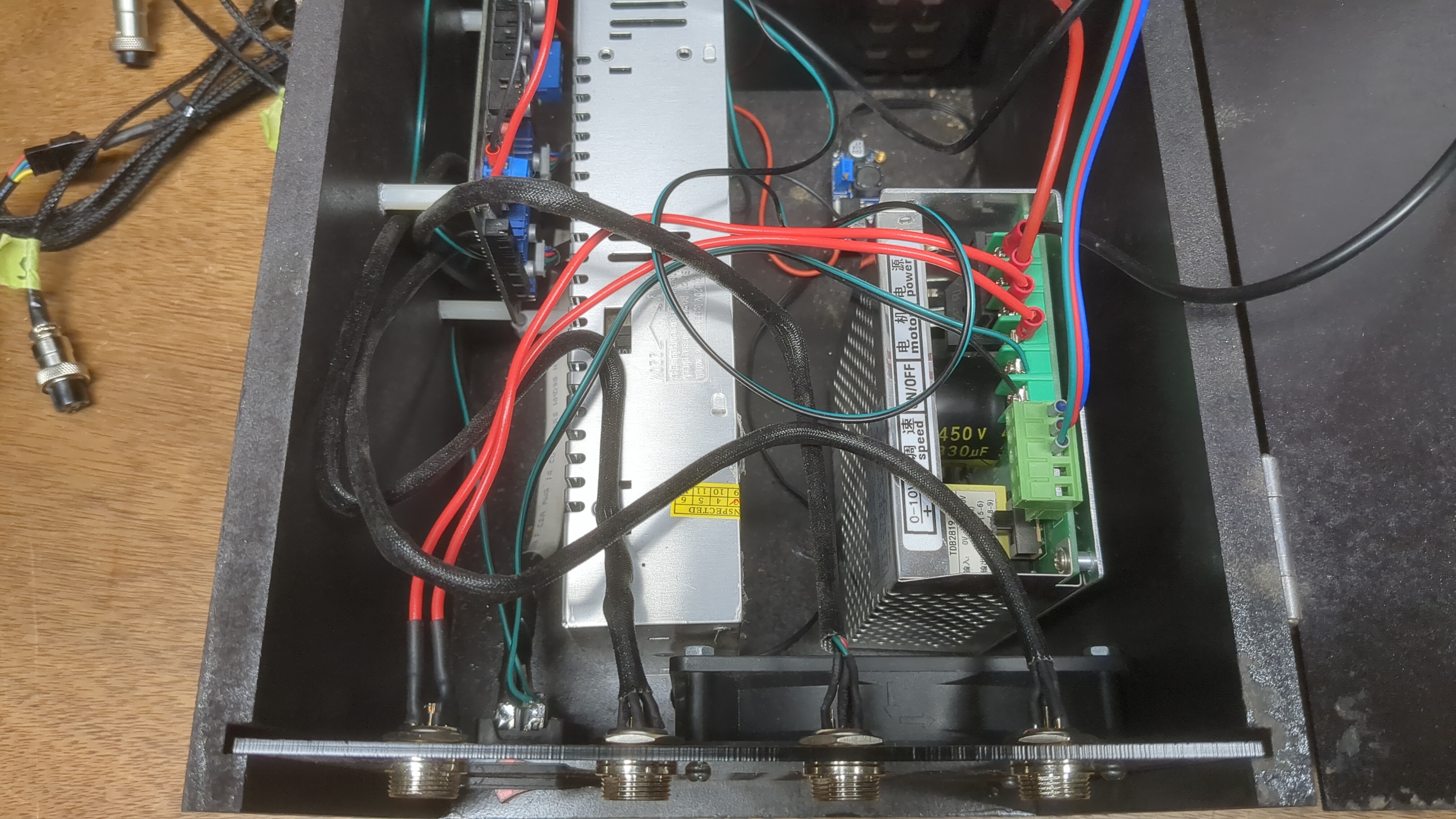
Then I had the joy of wiring and soldering a wiring harness. I also had to buy assortments of JST-SN connectors, and some plugins for the mains which included a fuse and a switch. Luckily I had some cable loom, heat shrink, wires, JST-PH connectors, XT-60s, high current wire, and other odds and ends to get this thing working. I also elected to use these nice screw-on airplane connectors from the enclosure to the mill for a good secure connection and ease of dissembled for storage. There's a lot I didn't mention like the types of wires the xt-90s for spindle (which i decided was a good idea to easily disconnect the wiring harness), and the cooling fan/ buck converter. If you are curious here's an image.
Setting up a PC
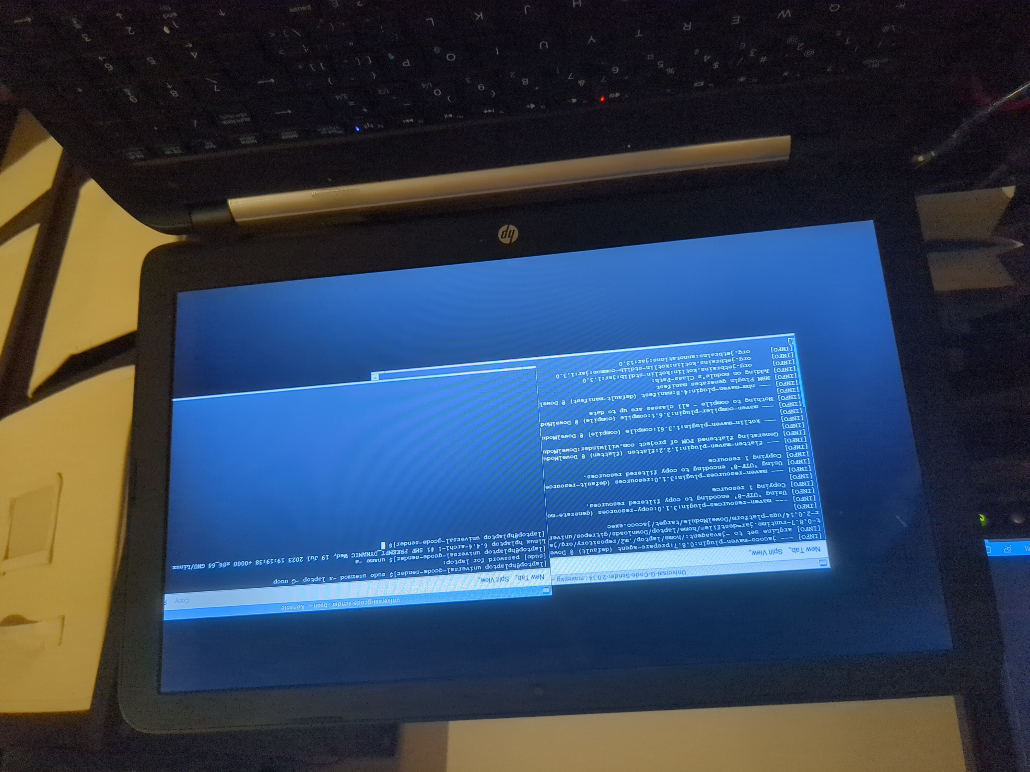
Whatever computer you use for UGS should probably be only for UGS as you don't want a Windows update or malicious website to interrupt your milling. One trick I sometimes use for these types of projects is an older laptop running a lightweight Linux distro (Arch Linux or Ubuntu Server works great). That way I can reduce the software down to an absolute minimum basically only running UGS and even increase the priority of UGS with the nice command to run before nonessential processes, effectively 100% of the CPU is focused on UGS. You don't need to do this by any means you can use an old dedicated Windows machine if you're less technically skilled with IT as well, but it should have minimal software especially the type that will interrupt UGS mid-way through a milling process.
Milling A Sign
Warning
Milling is dangerous with multiple hazards which can lead to bodily harm. As stated in the terms and conditions by reading this blog you agree the information is academic and not technical advice intended to be followed. If you do decide to do some milling, wiring, or anything else on this blog, you do so at your own risk.
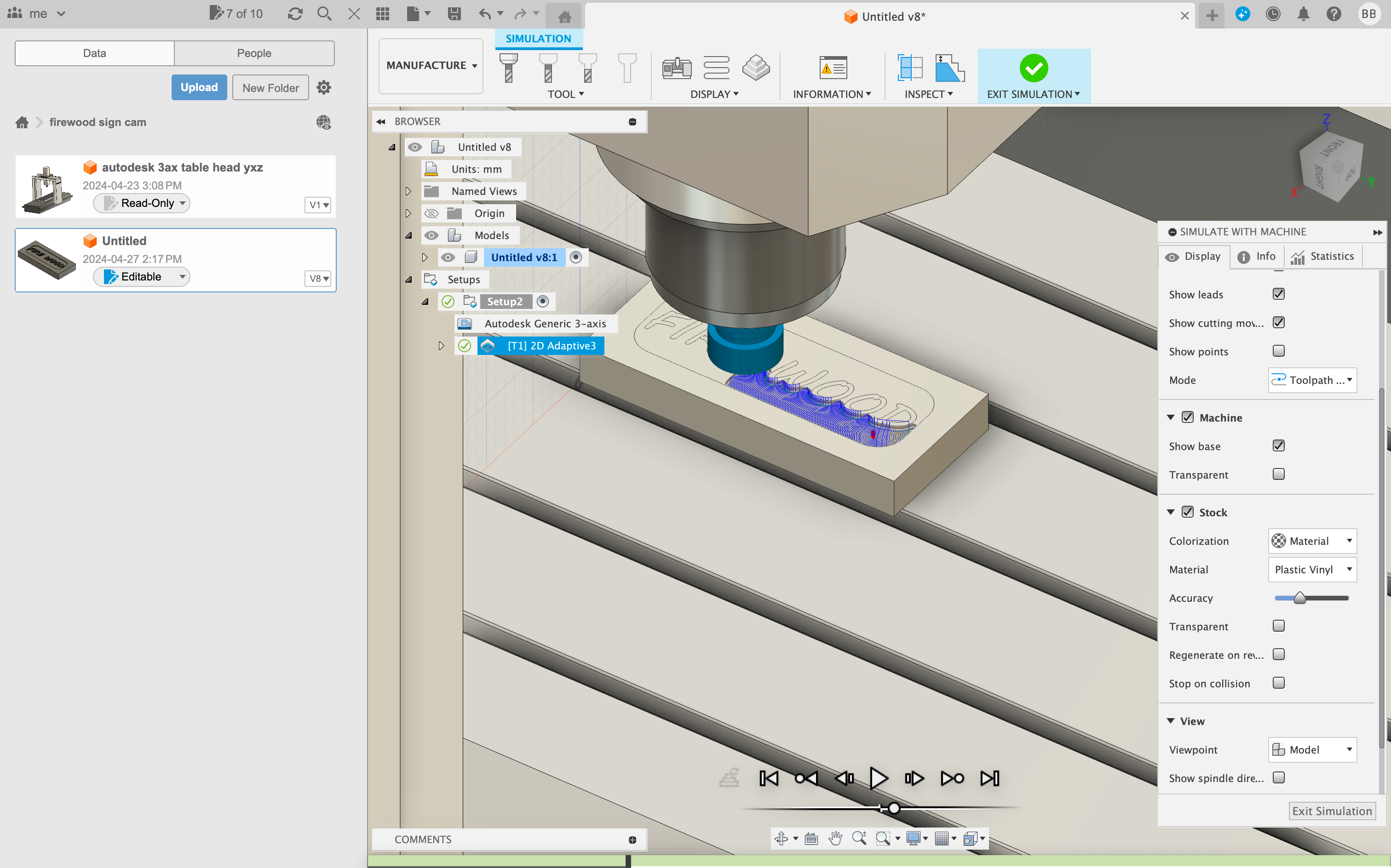
Finally, I got to dive into CAM software for which I was using Fusion 360. I use Fusion 360 because it's genuinely a great piece of software for CAD I just wish it was less web-based and would come to Linux. Anyway, it's also a great CAM software complete with a tools library. After a surprisingly easy learning curve, I was ready to mill anything I wanted with multiple tool changes. Some things to note:
- to create the Gcode or NC program as they call it. You need to select the correct target in the build window. In my case, it's GRBL which has its strain of Gcode as all machine firmware does). Multiple tools will result in multiple program loads after each tool change.
- In the same window, you also need to set how the machine should move to zero. This is important to avoid a crash I usually use clearance mode and pre-clear the machine (that way I can avoid a possible z ceiling crash if it auto clears too high).
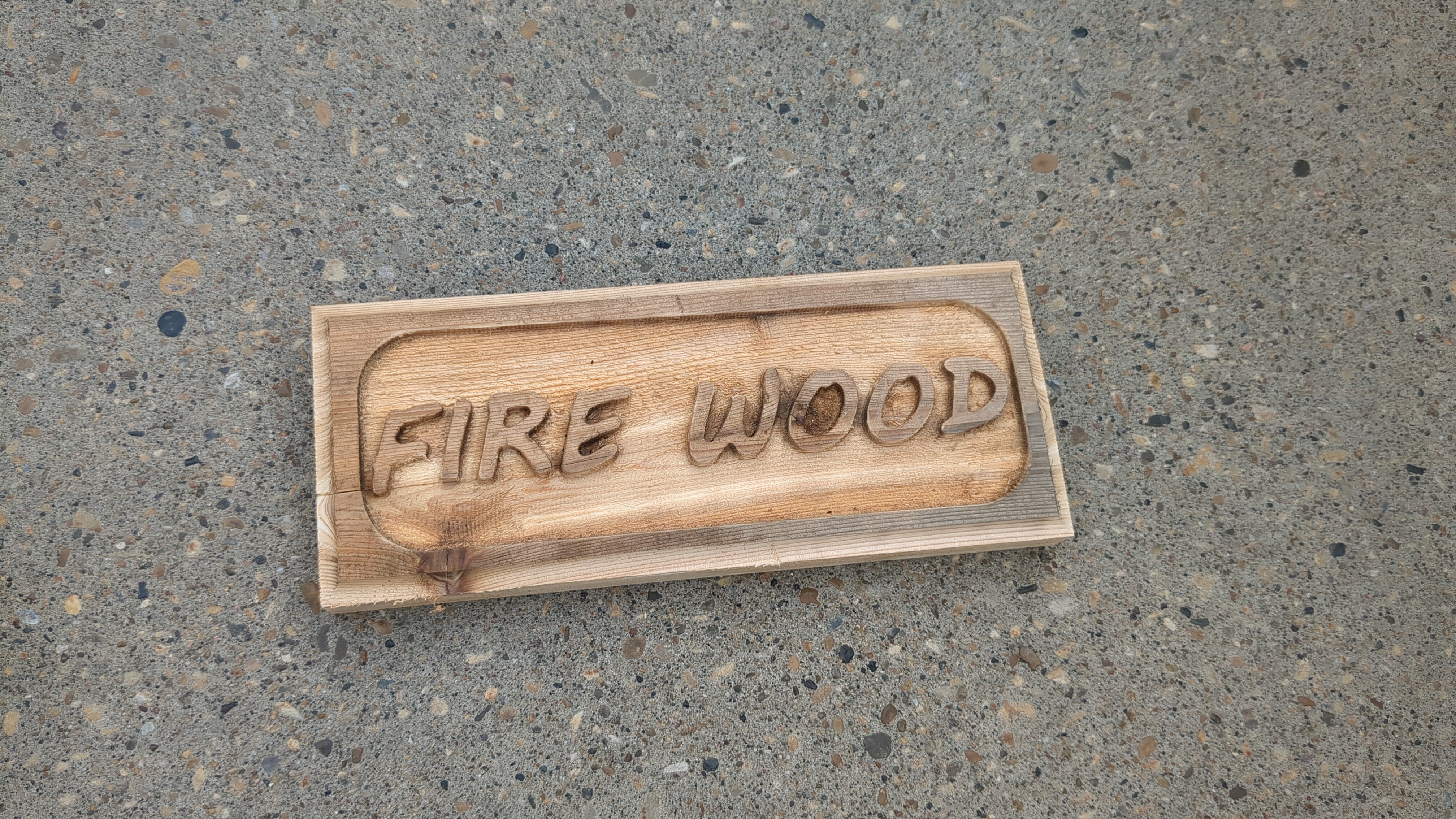
An important aspect of setting up this type of mill is properly securing the workpiece to spoil the board. I did get some of the included fastening/cantilever mechanisms, but with inexpensive cedar, I think it's better to precisely measure and drill holes into an oversized piece of cedar, then fasten it down with bolts and T-Slot nuts directly to the mill. Once the piece is done the excess can be cut away and I even hand-routed a nice fillet on the final edge. In the future when I try machining other materials like brass, walnut, and aluminum, I will probably use a drill press vice or possibly the included fasteners.
Once you have exported the GCode program from fusion360 (program.nc) you simply load the file into UGS. Before you hit run you need to zero the machine.
You can zero the machine in a few ways and I have a control board that can automate this, but i currently don't have a jig to zero the z-axis and limit switches for the x and y so i have to do it manually. Taking extra care, you should look a the visualizer on the right side window of UGS and move the x and y to the desired location. Then lower the z-axis down to the workpiece and reset the zero. If you selected clearance mode in Fusion 360 make sure you raise the bit as it assumes there's clearance between the piece and the bit at startup.
Warning
It would be very easy to get this part wrong and damage the mill. For instance, there is no auto-homing on this device (there are no limit switches like a 3D printer). Clicking the home button may destroy the mill if you're not careful. I have had zero crashes and incidents because I went slow and paid attention with my hand on the E-stop.
Now all that's left is to start the spindle by releasing the E-stop and turning the knob, then hitting start on UGS.
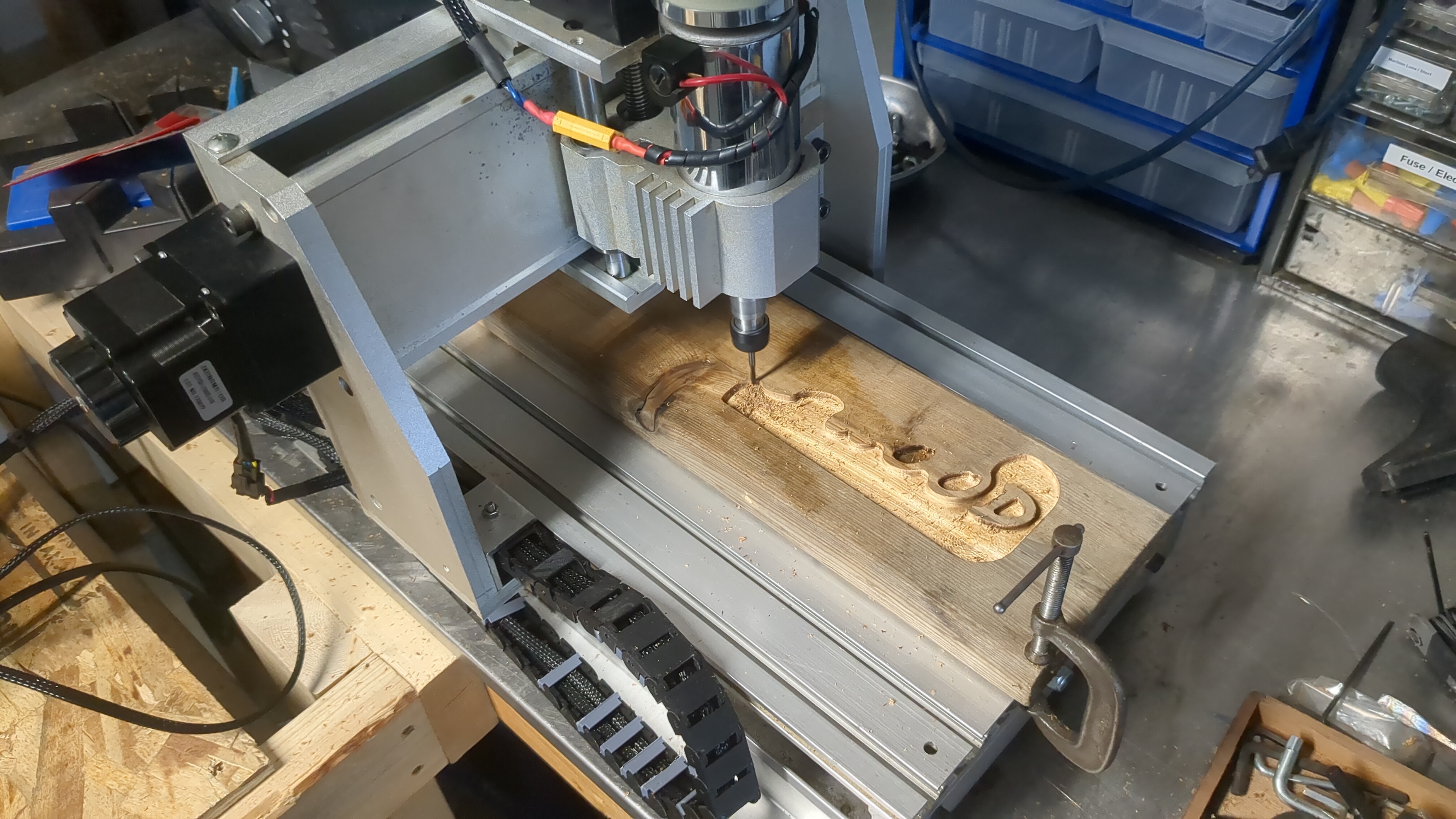
After experimenting a bit I got great results with a larger 1/4" flat nose 3 flute up-cut bit to mill out the larger areas, then I switched to a similar 1/8" bit for a little more detailed pass, both adaptive 2D clearing. I used a shop vac or compressed air to help evacuate wood chips as it cut.
Note
In the future I will get more tools, I'm especially excited about a larger cutting tool to deck down material quicker, and a 3D carving tool to add fillets and chamfers along with 3D designs on flat surfaces.
Great after some patience I had a few useful signs for the backyard.

Was it Worth While
In my honest opinion: it wasn't worth it because it took a long time to fix with lots of wiring, but I also don't regret it because I learned some things about wiring/soldering and I have wanted a mill since I can remember.
The reason I don't recommend it is multifaceted. For starters, it has a very small build surface (smaller than it looks) and is only really a wood-grade mill. I would have rather spent the time milling something for an innovative project rather than doing some basic wiring. Finally, let's be honest my enclosure is not that great; functional, but not a proper sheet metal enclosure. Nonetheless, fixing/modding something is also satisfying and now I have a 1000$ (CAD) mill which I paid less than 500$ plus some of my time.
Conculsion
I'm hoping to post some more pieces soon. I would love to make a 3D sign for the workshop out of a Walnut cutoff, and I would also like to try building some mechanical objects like planetary gears and enclosures. I am particularly excited to try some techniques I have only seen used by smartphone manufacturers, but that require some more equipment. My next project will be a simple heat sink for my DIY e-skate from some salvaged aluminum. Lots to learn, lots to experiment with, and lots of money to spend in the future.